
![]()
Chamberlain C2102 Garage Door Opener
Preparation
WARNING: To prevent possible SERIOUS INJURY or DEATH:
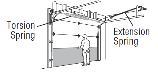
- ALWAYS call a trained door systems technician if the garage door binds, sticks, or is out of balance. An unbalanced garage door may NOT reverse when required.
- NEVER try to loosen, move, or adjust the garage door, door springs, cables, pulleys, brackets, or their hardware, ALL of which are under EXTREME tension.
- Disable ALL locks and remove ALL ropes connected to the garage door BEFORE installation and operating the garage door opener to avoid entanglement.
- DO NOT install on a one-piece door if using devices or features providing unattended closing. Unattended devices and features are to be used ONLY with sectional doors.
Before you begin:
- Disable locks and remove any ropes connected to the garage door
- Lift the door halfway up. Release the door. If balanced, it should stay in place, supported entirely by its springs.
- Raise and lower the door to check for binding or sticking. If your door binds, sticks, or is out of balance, call a trained door systems technician.
- Check the seal on the bottom of the door. Any gap between the floor and the bottom of the door must not exceed 1/4″ (6 mm). Otherwise, the safety reversal system may not work properly.
- The opener should be installed above the center of the door. If there is a torsion spring or center bearing plate in the way of the header bracket, it may be installed within 4 feet (1.2 m) to the left or right of the door center. See page 13.

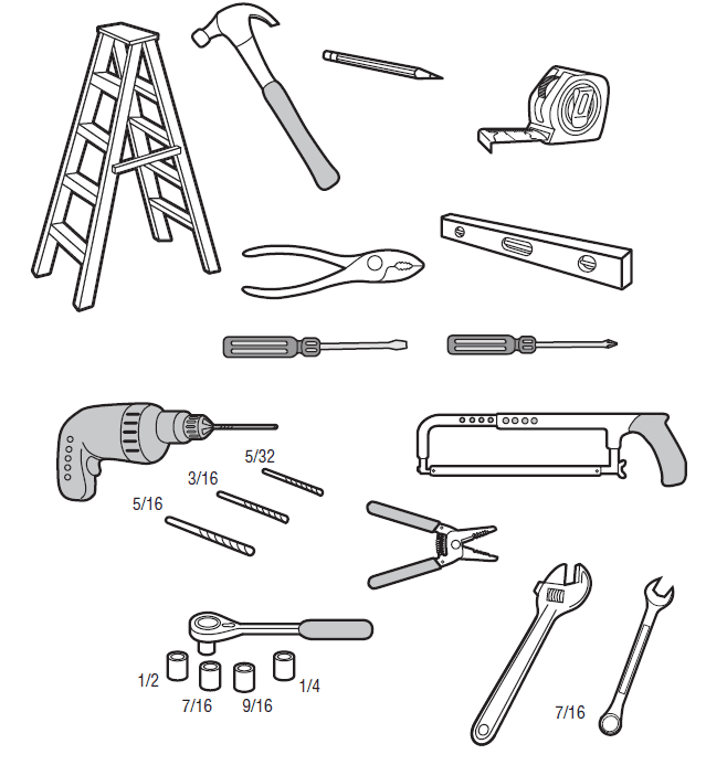
Tools Needed
Additional Items You May Need:
Survey your garage area to see if you will need any of the following items:
- (2) 2X4 Pieces of wood: May be used to fasten the header bracket to the structural supports, also used to position the garage door opener during installation and for testing the safety reversing sensors.
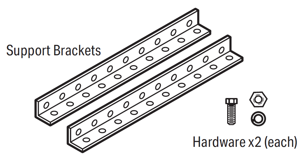
- Support bracket and fastening hardware: Must be used if you have a finished ceiling in your garage.

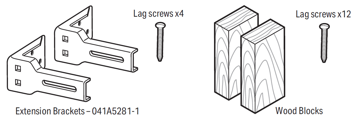
- Extension brackets (Model 041A5281-1) or wood blocks: Depending upon garage construction, extension brackets or wood blocks may be needed to install the safety reversing sensor.

- Fastening hardware: Alternate floor mounting of the safety reversing sensor will require hardware not provided.
- Door reinforcement: Required if you have a lightweight steel, aluminum, fiberglass or glass panel door.
- Rail extension kit: Required if your garage door is more than 7 feet (2.13 m) high.
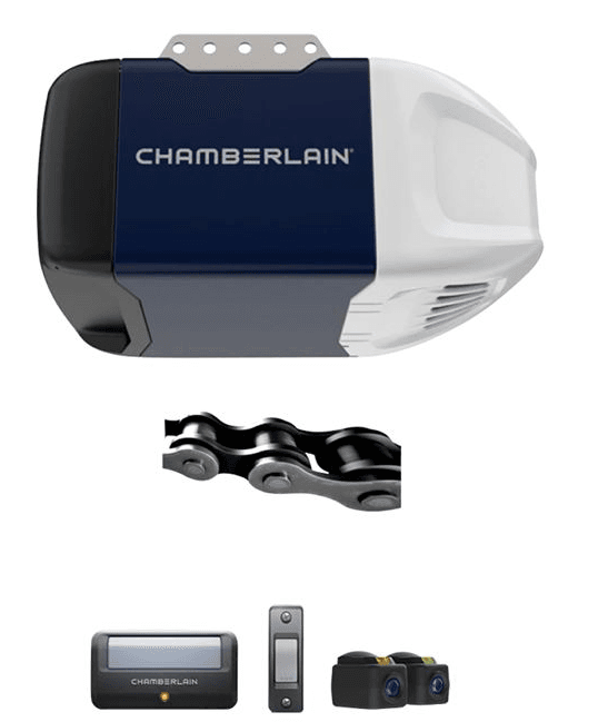
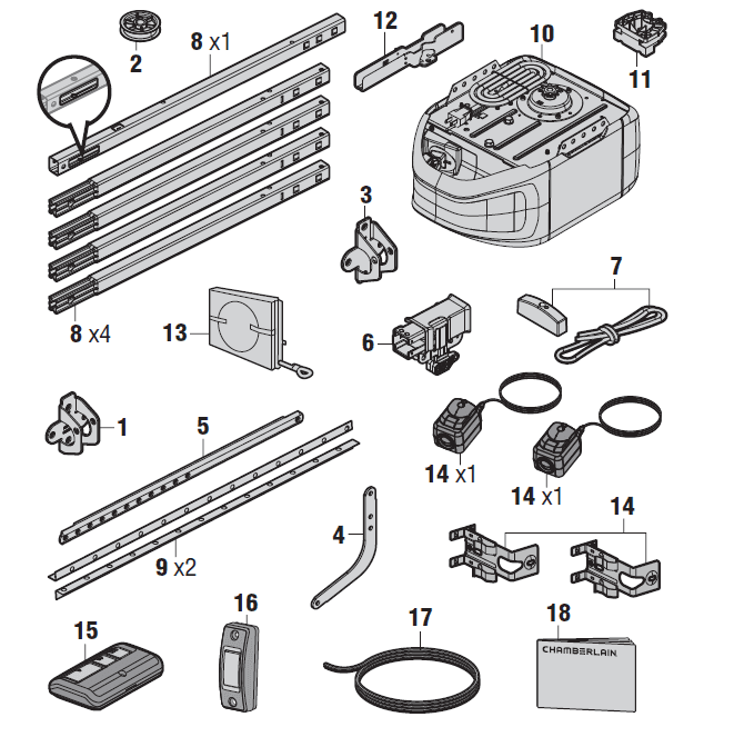
Carton Inventory
Save the carton and packing material until the installation and adjustment is complete. Instructions for the accessories will be attached to the accessory and are not included in this manual. The images throughout this manual are for reference only and your product may look different.
- Header bracket
- Pulley
- Door bracket
- Curved door arm
- Straight door arm (Packaged inside front rail section)
- Trolley
- Emergency release rope and handle
- Rail (1 front and 4 center sections)
- Hanging brackets (2) (Packaged inside the front rail section)
- Garage door opener (motor unit)
- Chain spreader with screws
- “U” bracket
- Chain and cable
- The Protector System® Safety reversing sensors with 2 conductor white and white/black wire attached: sending sensor (1), receiving sensor (1), and safety sensor brackets (2)
- Remote control
- Push button door control
- White and red/white wire
- Installation manual and all warning labels See Hardware page 6.
Go to chamberlain.com for replacement or additional accessories: 3-button remote control model 953EV-P2 Wireless keypad model 940EV-P2
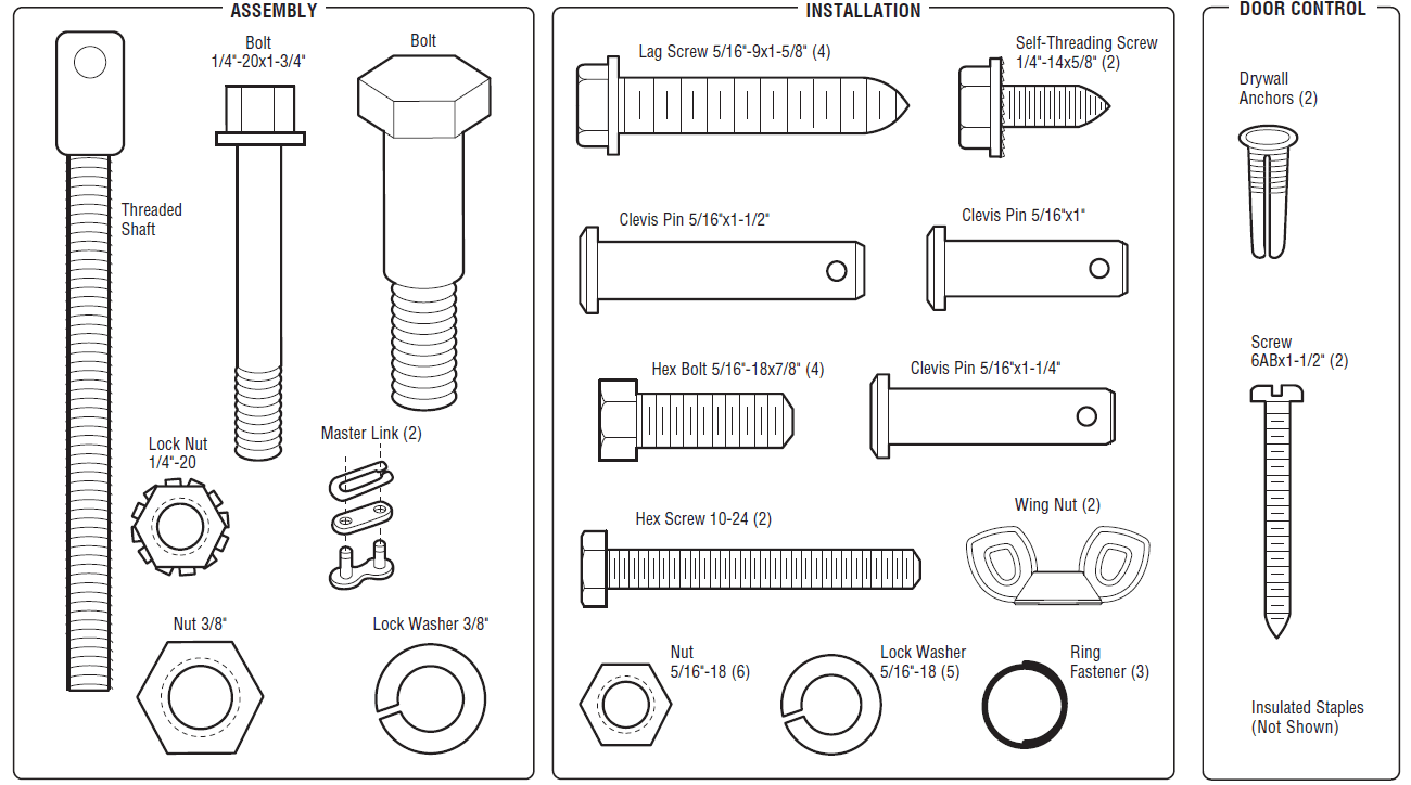
Hardware
Assembly
STEP 1: Assemble the Rail and Install the Trolley
To avoid installation difficulties, do not run the garage door opener until instructed to do so.
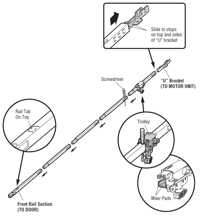
The front rail has a cut-out “window” at the door end. The rail tab MUST be on top of the rail when assembled.
- Remove the straight door arm and hanging bracket packaged inside the front rail and set aside for Installation Steps 5 and 9.
NOTE: To prevent INJURY while unpacking the rail, carefully remove the straight door arm stored within the rail section. - Align the rail sections on a flat surface as shown and slide the tapered ends into the larger ones. Tabs along the side will lock into place.
- Place the motor unit on packing material to protect the cover, and rest the back end of the rail on top. For convenience, put a support under the front end of the rail.
- As a temporary stop, insert a screwdriver into the hole in the second rail section from the motor unit, as shown.
- Check to be sure there are 4 plastic wear pads inside the inner trolley. If they became loose during shipping, check all the packing material. Snap them back into position as shown.
- Slide the trolley assembly toward the screwdriver as shown.
- Slide the rail onto the “U” bracket until it reaches all the stops on the top and sides of the “U” bracket.

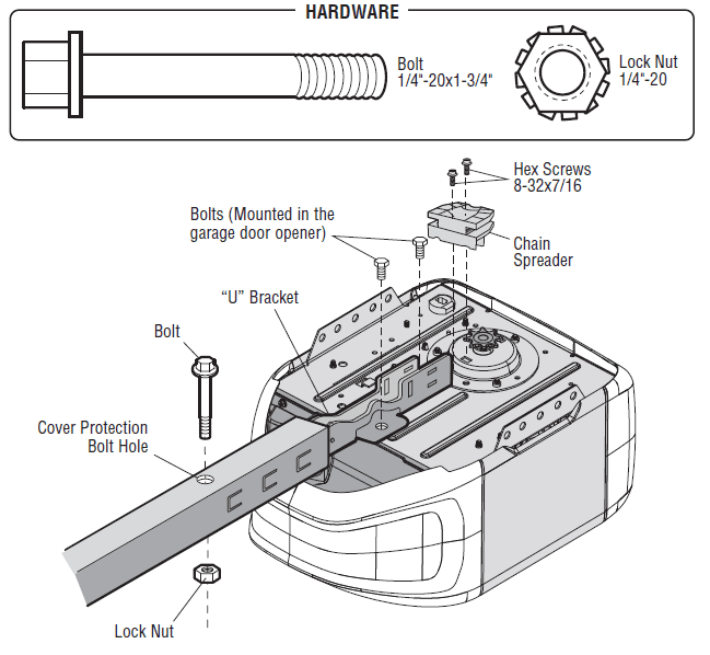
STEP 2 Fasten the Rail to the Motor Unit
- Insert a 1/4″-20 x 1-3/4″ bolt into the cover protection bolt hole on the back end of the rail as shown. Tighten securely with a 1/4″-20 lock nut. DO NOT overtighten.
- Remove the bolts from the top of the motor unit.
- Use the carton to support the front end of the rail.
- Place the “U” bracket, flat side down, onto the motor unit and align the bracket holes with the bolt holes.
- Fasten the “U” bracket with the previously removed bolts; DO NOT use any power tools. The use of power tools may permanently damage the garage door opener.
- Attach chain spreader to the motor unit with two screws.

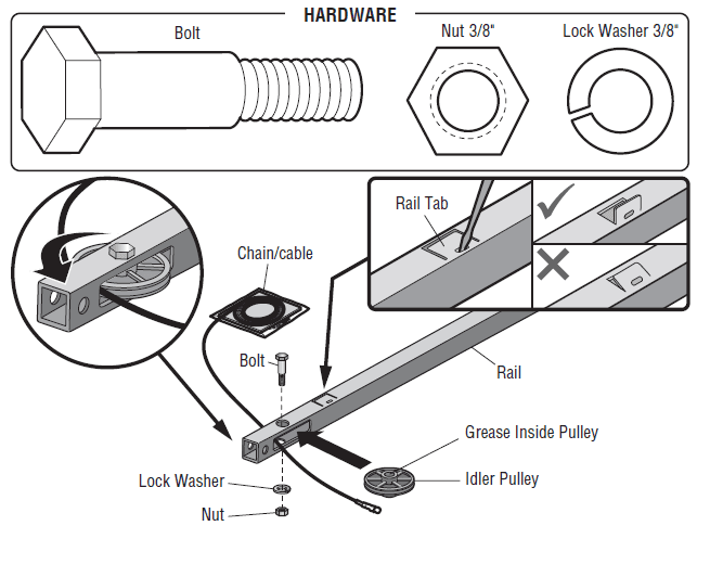
STEP 3: Install the Idler Pulley
- Lay the chain/cable beside the rail, as shown. Grasp the end of the cable and pass approximately 12″ (30 cm) of cable through the window. Allow it to hang until Assembly Step 4.
- Remove the tape from the idler pulley. The inside center should be pre-greased. If dry, re-grease to ensure proper operation.
- Place the idler pulley into the window as shown.
- Insert the idler bolt from the top through the rail and pulley. Tighten with a 3/8″ lock washer and nut underneath the rail until the lock washer is compressed.
- Rotate the pulley to be sure it spins freely.
- Locate the rail tab. The rail tab is near the idler pulley on the front rail section. Use a flat-head screwdriver and lift the rail tab until the tab is vertical (90º).

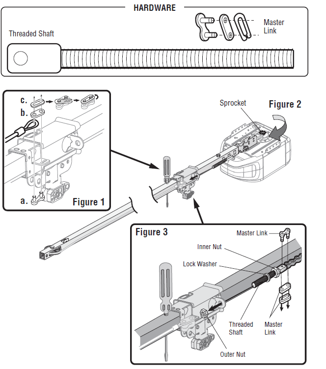
STEP 4: Install the Chain
- Pull the cable around the idler pulley and toward the trolley.
- Connect the cable to the retaining slot on the trolley, as shown. (Figure 1)
- Push the pins of the master link bar through the cable link and trolley slot.
- Push the master link cap over the pins and past the pin notches.
- Slide the closed end of the clip-on spring over one of the pins. Push the open end of the clip-on spring onto the other pin.
- With the trolley against the screwdriver, dispense the remainder of the cable/chain along the rail toward the motor unit around the sprocket, and continuing to the trolley assembly. The sprocket teeth must engage the chain. (Figure 2)
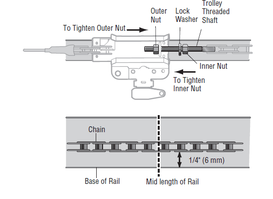
- Check to make sure the chain is not twisted, then connect it to the threaded shaft with the remaining master link.
- Thread the inner nut and lock washer onto the trolley’s threaded shaft.
- Insert the trolley threaded shaft through the hole in the trolley. Be sure the chain is not twisted. (Figure 3)
- Loosely thread the outer nut onto the trolley threaded shaft.
- Remove the screwdriver.

STEP 5 Tighten the Chain
- Spin the inner nut and lock washer down the trolley threaded shaft, away from the trolley.
- To tighten the chain, turn the outer nut in the direction shown.
- When the chain is approximately 1/4″ (6 mm) above the base of the rail at it’s midpoint, retighten the inner nut to secure the adjustment.
Sprocket noise can result if the chain is too loose. When installation is complete, you may notice some chain droop with the door closed. This is normal. If the chain returns to the position shown when the door is open, do not re-adjust the chain.
NOTE: During future maintenance, ALWAYS pull the emergency release handle to disconnect the trolley before adjusting the chain. You have now finished assembling your garage door opener. Please read the following warnings before proceeding to the installation section.
Installation
To reduce the risk of SEVERE INJURY or DEATH:
- READ AND FOLLOW ALL INSTALLATION WARNINGS AND INSTRUCTIONS.
- Install the garage door opener ONLY on a properly balanced and lubricated garage door. An improperly balanced door may NOT reverse when required and could result in SEVERE INJURY or DEATH.
- ALL repairs to cables, spring assemblies, and other hardware MUST be made by a trained door systems technician BEFORE installing the opener.
- Disable ALL locks and remove ALL ropes connected to the garage door BEFORE installing the opener to avoid entanglement.
- Where possible, install the door opener 7 feet (2.13 m) or more above the floor.
- Mount the emergency release within reach, but at least 6 feet (1.83 m) above the floor, and avoid contact with vehicles to avoid accidental release.
- NEVER connect the garage door opener to a power source until instructed to do so.
- NEVER wear watches, rings, or loose clothing while installing or servicing the opener. They could be caught in garage door or opener mechanisms.
- Install a wall-mounted garage door control:
- within sight of the garage door.
- out of reach of small children at a minimum height of 5 feet (1.5 m) above floors, landings, steps, or any other adjacent walking surface.
- away from ALL moving parts of the door.
- Place an entrapment warning label on the wall next to the garage door control in a prominent location.
- Place emergency release/safety reverse test label in plain view on the inside of the garage door.
- Upon completion of installation, test the safety reversal system. Door MUST reverse on contact with a 1- 1/2″ (3.8 cm) high object (or a 2×4 laid flat) on the floor.
- DO NOT install on a one-piece door if using devices or features providing unattended closing. Unattended devices and features are to be used ONLY with sectional doors.
- SAVE THESE INSTRUCTIONS.
STEP 1: Determine the Header Bracket Location
Installation procedures vary according to garage door types. Follow the instructions that apply to your door.
- Close the door and mark the inside vertical centerline of the garage door.
- Extend the line onto the header wall above the door. You can fasten the header bracket within 4 feet (1.22 m) of the left or right of the door center only if a torsion spring or center bearing plate is in the way; or you can attach it to the ceiling (see page 14) when clearance is minimal. (It may be mounted on the wall upside down if necessary, to gain approximately 1/2″ (1 cm). If you need to install the header bracket on a 2×4 (on wall or ceiling), use lag screws (not provided) to securely fasten the 2×4 to structural supports as shown here and on page 14.
- Open your door to the highest point of travel as shown. Draw an intersecting horizontal line on the header wall 2″ (5 cm) above the high point:
- 2″ (5 cm) above the high point for sectional door and one-piece door with track.
- 8″ (20 cm) above the high point for a one-piece door without track.
This height will provide travel clearance for the top edge of the door. NOTE: If the total number of inches exceeds the height available in your garage, use the maximum height possible, or refer to page 14 for ceiling installation.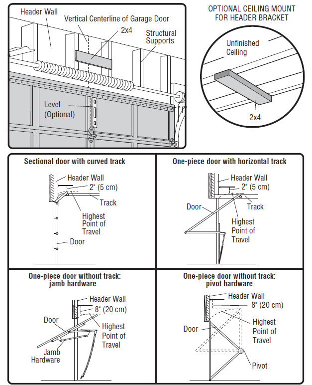
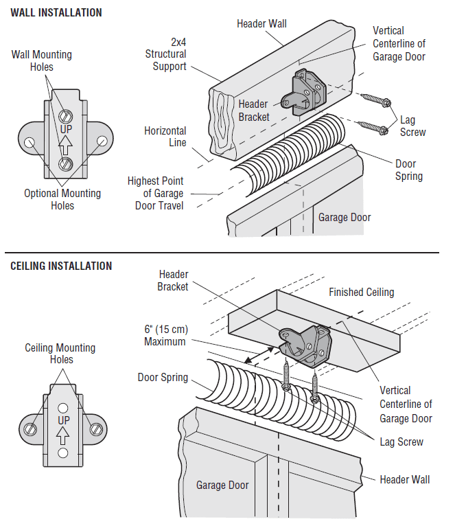
STEP 2: Install the Header Bracket
You can attach the header bracket either to the wall above the garage door or to the ceiling. Follow the instructions that will work best for your particular requirements. Do not install the header bracket over drywall. If installing into masonry, use concrete anchors (not provided).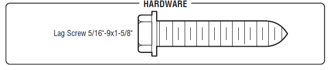
OPTION A – WALL INSTALLATION
- Center the bracket on the vertical centerline with the bottom edge of the bracket on the horizontal line as shown (with the arrow pointing toward the ceiling).
- Mark the vertical set of bracket holes. Drill 3/16″ pilot holes and fasten the bracket securely to a structural support with the hardware provided.
OPTION B – CEILING INSTALLATION
- Extend the vertical centerline onto the ceiling as shown.
- Center the bracket on the vertical mark, no more than 6″ (15 cm) from the wall. Make sure the arrow is pointing away from the wall. The bracket can be mounted flush against the ceiling when clearance is minimal.
- Mark the side holes. Drill 3/16″ pilot holes and fasten the bracket securely to a structural support with the hardware provided.

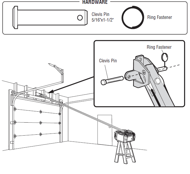
STEP 3: Attach the Rail to the Header Bracket
- Position the opener on the garage floor below the header bracket. Use packing material as a protective base.
NOTE: If the door spring is in the way, you will need help. Have someone hold the opener securely on a temporary support to allow the rail to clear the spring. - Position the rail bracket against the header bracket.
- Align the bracket holes and join with a clevis pin as shown.
- Insert a ring fastener to secure.

STEP 4 Position the Garage Door Opener
- Remove the packing material and lift the garage door opener onto a ladder.
- Fully open the door and place a 2×4 (laid flat) under the rail. For one-piece doors without tracks, lay the 2×4 on it’s side.
NOTE: A 2×4 is ideal for setting the distance between the rail and the door. If the ladder is not tall enough, you will need help at this point. If the door hits the trolley when it is raised, pull the trolley release arm down to disconnect the inner and outer trolley. Slide the outer trolley toward the garage door opener. The trolley can remain disconnected until instructed.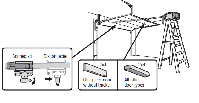
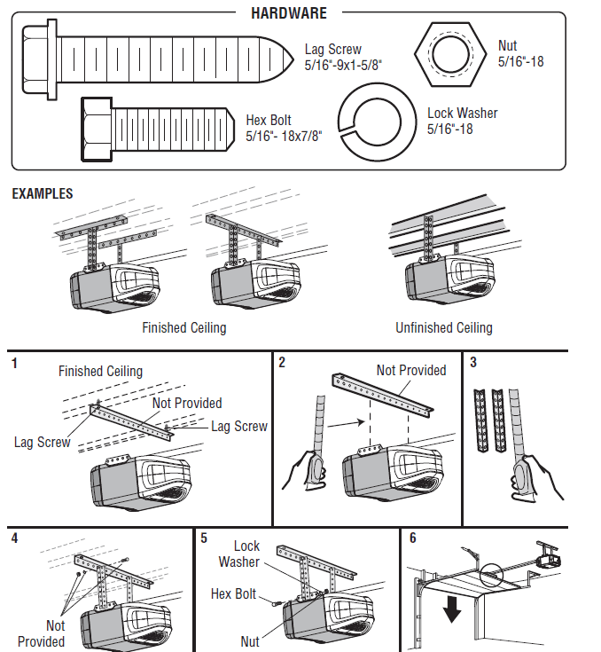
STEP 5 Hang the Garage Door Opener
Hanging the garage door opener will vary depending on your garage. Below are three example installations. Your installation may be different. For ALL installations, the garage door opener MUST be connected to structural supports. The instructions illustrate one of the examples below.
- On finished ceilings, use the lag screws to attach a support bracket (not provided) to the structural supports before installing the garage door opener.
- Make sure the garage door opener is aligned with the header bracket. Measure the distance from each side of the garage door opener to the support bracket.
- Cut both pieces of the hanging bracket to the required lengths.
- Attach the end of each hanging bracket to the support bracket with appropriate hardware (not provided).
- Attach the garage door opener to the hanging brackets with the hex bolts, lock washers, and nuts.
- Remove the 2×4 and manually close the door. If the door hits the rail, raise the header bracket.

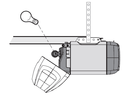
STEP 6: Install the Light Bulb
CAUTION: To prevent possible OVERHEATING of the end panel or light socket:
- Use ONLY A19 light bulbs.
- DO NOT use incandescent bulbs larger than 100W.
- DO NOT use compact fluorescent light bulbs larger than 26W (100W equivalent).
- DO NOT use halogen bulbs.
- DO NOT use short neck or specialty light bulbs.
LED bulbs may cause remote control radio interference. Use ONLY LED bulbs recommended here: chamberlain.com/bulb.
- Pull the light lens down.
- Insert light bulb.
- Close the light lens.

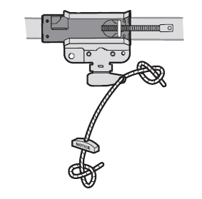
STEP 7: Attach the Emergency Release Rope and Handle
WARNING: To prevent possible SERIOUS INJURY or DEATH from a falling garage door:
- If possible, use the emergency release handle to disengage the trolley ONLY when the garage door is CLOSED. Weak or broken springs or an unbalanced door could result in an open door falling rapidly and/or unexpectedly.
- NEVER use the emergency release handle unless the garage doorway is clear of persons and obstructions.
- NEVER use the handle to pull the door open or closed. If the rope knot becomes untied, you could fall.
- Insert one end of the emergency release rope through the handle. Make sure that “NOTICE” is right side up. Secure with an overhand knot at least 1″ (2.5 cm) from the end of the rope to prevent slipping.
- Insert the other end of the emergency release rope through the hole in the trolley release arm. Mount the emergency release within reach, but at least 6 feet (1.83 m) above the floor, avoiding contact with vehicles to prevent accidental release, and secure with an overhand knot.
NOTE: If it is necessary to cut the emergency release rope, seal the cut end with a match or lighter to prevent unraveling. Ensure the emergency release rope and handle are above the top of all vehicles to avoid entanglement.
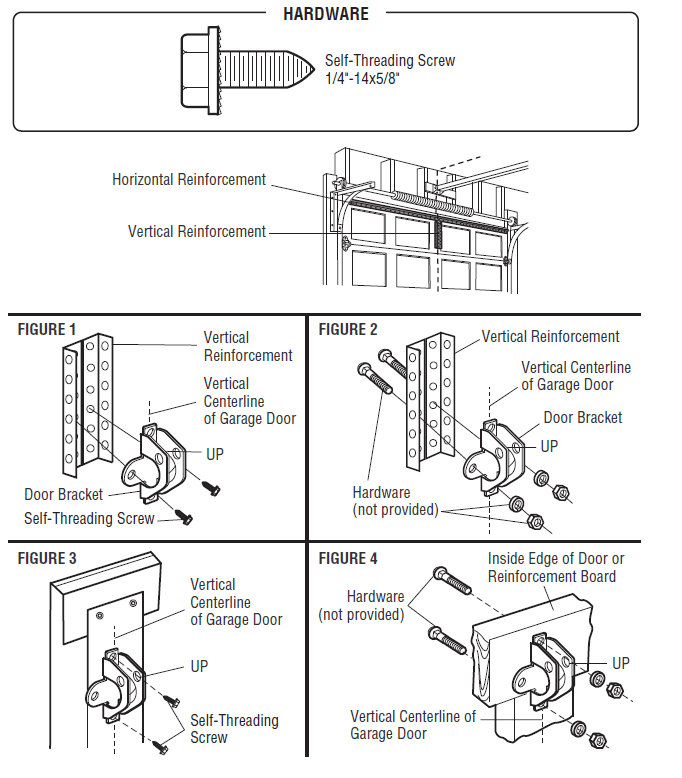
STEP 8: Install the Door Bracket
Horizontal and vertical reinforcement is needed for lightweight garage doors (fiberglass, aluminum, steel, doors with glass panels, etc.) (not provided). A horizontal reinforcement brace should be long enough to be secured to two or three vertical supports. A vertical reinforcement brace should cover the height of the top panel. Contact the garage door manufacturer or installing dealer for opener reinforcement instructions or a reinforcement kit.
NOTE: Many door reinforcement kits provide for the direct attachment of the clevis pin and door arm. In this case, you will not need the door bracket; proceed to the next step.
OPTION A – SECTIONAL DOORS
- Center the door bracket on the previously marked vertical centerline used for the header bracket installation. Note the correct UP placement, as stamped inside the bracket.
- Position the top edge of the bracket 2″-4″ (5-10 cm) below the top edge of the door, OR directly below any structural support across the top of the door.
- Mark, drill holes, and install as follows, depending on your door’s construction.
Metal or lightweight doors using a vertical angle iron brace in the door panel support and the door bracket:
- Drill 3/16″ fastening holes. Secure the door bracket using the two 1/4″-14×5/8″ self-threading screws. (Figure 1)
- Alternately, use two 5/16″-18×2″ bolts, lock washers, and nuts (not provided). (Figure 2)
Metal, insulated, or light-weight factory reinforced doors:
- Drill 3/16″ fastening holes. Secure the door bracket using the self-threading screws. (Figure 3) Wood doors:
- Use top and bottom or side-to-side door bracket holes. Drill 5/16″ holes through the door and secure bracket with 5/16″-18×2″ carriage bolts, lock washer,s and nuts (not provided). (Figure 4)
NOTE: The 1/4″-14×5/8″ self-threading screws are not intended for use on wood doors.
Troubleshooting
Diagnostic Chart
Your garage door opener is programmed with self-diagnostic capabilities. The UP and DOWN arrows on the garage door opener flash the diagnostic codes.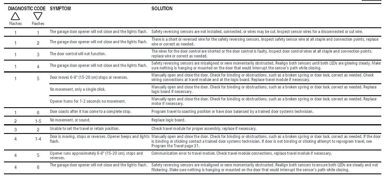
Additional Troubleshooting
My garage door opener stops, reverses, beeps, and flashes its lights:
- Check for binding or obstructions anywhere along the track to the garage floor.
My remote control will not activate the garage door:
- Verify the lock feature is not activated on the door control.
- Reprogram the remote control.
- If the remote control still will not activate the door, check the diagnostic codes to ensure the garage door opener is working properly.
My door will not close and the lights blink on my opener:
The safety reversing sensor must be connected and aligned correctly before the garage door opener can move in the down direction.
- Check for binding or obstructions anywhere along the track to the garage floor.
- The safety reversing sensor must be connected and aligned correctly before the garage door opener can move in the down direction.
- Verify that the safety reversing sensors are properly installed, aligned, and free of any obstructions.
- If the receiving sensor (green LED) faces direct sunlight, switch the receiving sensor with the sending sensor so that the receiving sensor is not in direct sunlight.
For more manuals by Chamberlain, visit ManualsLibraryy