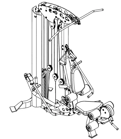
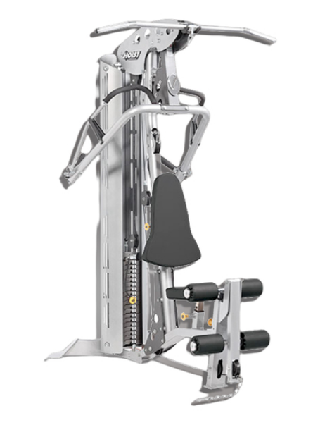
HoistFitness V5 Home Gym
TOOLS REQUIRED
- Socket Wrench
- 1/2, 9/16″, and 3/4″ Sockets
- Crescent Wrench
- Rubber Mallet
- Tape Measure
FRAME ASSEMBLY
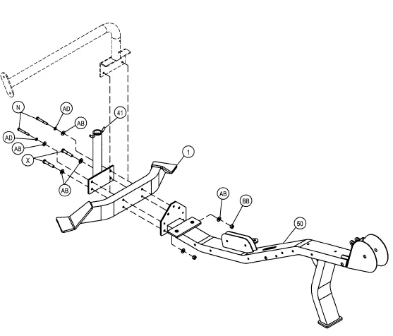
Start assembly by bolting (41) and (50) on opposite sides of (1) as shown. Wrench Tighten bolts.
Part Description
- 1 – Rear Support Foot
- 41 – Accessory Rack
- 50 – Base Assembly
Hardware Descriptions
- N – 3/8″-16UNC x 3″ HHB (WZ)
- X – 3/8-16UNC x 3 1/4″ HHB (WZ)
- AB – 3/8 USS Flat Washer (WZ)
- AD – 3/8″ Split Lock Washer (WZ)
- BB – 3/8-16UNC Thin Nylok Nut (WZ)

If you are installing a leg press option, refer to the leg press owner’s manual and assemble the leg press frame parts at this time.
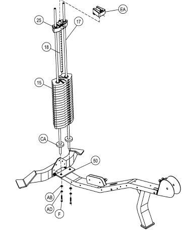
Start assembly by bolting (l 7)’s to (50). Then slide (CA) onto each (17) followed by nineteen (15)’s. Finally, slide (25) onto the stack.
Part Descriptions
- 15 – 1 0lbs. Intermediate Radial Weight
- 17 – Guide Rod(. 75 dia X 71.44″)
- 18 – 21 Hole Weight Stem
- 25 – 8.50 lbs Cast Radial Top Weight
- 50 – Base Assembly
Hardware Descriptions
- F – 3/8″-16UNC x 1 1/4″ HHB (WZ)
- AB – 3/8 USS Flat Washer (WZ)
- AD – 3/8″ Split Lock Washer (WZ)
- CA – 1/2″ Thick Weight Stack Bumper
- EA – 2 l/2LB Add On Weight

The 2 1/2 LB Add-on Weights are used by saddling one on top of the Top Weight and then, if so desired, another on top of the Add-on Weight. This allows you to do smaller incremental weight increases.
Be sure to only thread the bolt halfway. Bolt will be tightened in a later step.
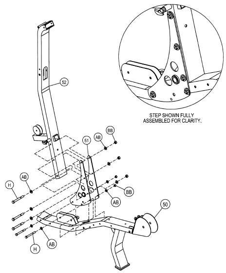
Attach (51) to (50). Next place (52) between (51), and attach. Hand-tighten bolts; they will be tightened in a later step.
Part Descriptions
- 50 – Base Assembly
- 51 – Bottom Upright Support
- 52 – Main Upright
Hardware Descriptions
- H – 3/8″-16UNC x 5″ HHB (WZ)
- AB – 3/8 USS Flat Washer (WZ)
- BB – 3/8-16UNC Thin Nylok Nut (WZ)

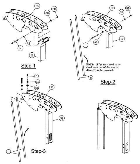
In this assembly, start by positioning (53) to (52). Then, bolt (53) to (17). Wrench Tighten all bolts up to this point.
Part Descriptions
- 17 – Guide Rod(. 75 dia X 71.44)
- 51 – Bottom Upright Support
- 52 – Main Upright Assembly
- 53 – Top Frame Assembly
Hardware Descriptions
- F – 3/8″-16UNC x 1 1/4″ HHB (WZ)
- H – 3/8″-16UNC x 5″ HHB (WZ)
- AB – 3/8 USS Flat Washer (WZ)
- AD – 3/8 Split Lock Washer (WZ)
- BB – 3/8-16UNC Thin Nylok Nut (WZ)

Start by attaching the backside of (12) to (53) and let the front of (12) hang downward; it will he assembled in a later step. Hand Tighten the bolt.
Part Descriptions
- 12 – Bar Mount Assembly
- 53 – Top Frame Assembly
Hardware Descriptions
- H – 3/8″-16UNC x 5″ HHB (WZ)
- AB – 3/8 USS Flat Washer (WZ)
- BB – 3/8-16UNC Thin Nylok Nut (WZ)

In Step: 2f-l attach (54) to (50). Wrench Tighten bolts. In Step: 2f-2 attach (55) to (50). Wrench tighten bolt then loosen enough so (55) pivots freely.
Part Descriptions
- 50 – Base Assembly
- 54 – Cable Anchor
- 55 – Pully Swivel Assembly
Hardware Descriptions
- ‘U – 3/8″-16UNC x 4 3/4″ HHB (WZ)
- B1- 1/2″-13UNC x 3 1/2″ HHB (WZ)
- AA – 1/2 SAE Flat Washer (WZ)
- AB – 3/8 USS Flat Washer (WZ)
- BA – 1/2-13UNC Thin Nylok Nut (WZ)
- BB – 3/8-16UNC Thin Nylok Nut (WZ)

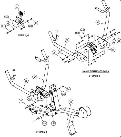
In Step: 2g-l attach (CD) to (56). Wrench Tighten bolts. In Step: 2g-2 attach (57) and (58) to (56). Hand Tighten bolts; they will he tightened later. In Step: 2g-3 slide (59) into (51) as shown. Next, attach the fully assembled arms from step 2g-2 to ( 51) as shown. Wrench tighten bolts.
Part Descriptions
- 50 – Base Assembly
- 51 – Bottom Upright Support Assy.
- 56 – Arm Pivoting Linkage Assy.
- 57 – Right Arm Assembly
- 58 – Left Arm Assembly
- 59 – 01.00 X 5.37 CRS Axle
Hardware Descriptions
- E1 – 1/2-13UNC x 6 3/8″ HHB (WZ)
- F1 – 3/8-16UNC x 2″ HHB (WZ)
- J1 – 3/8-16UNC x I” HHB (WZ)
- AA – 1/2 SAE Flat Washer (WZ)
- AB – 3/8 USS Flat Washer (WZ)
- BA – 1/2-13UNC Thin Nylok Nut (WZ)
- BB – 3/8-16UNC Thin Nylok Nut (WZ)
- CD – 03 1/2″ Standard Pulley

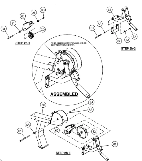
In Step 2h-1: insert (21) into (60). Attach (CD) to (60). Wrench Tighten the bolt. In Step 2h-2: attach (62) to (61). Wrench Tighten the bolt, then loosen enough so that (62) pivots freely. In Step 2h-3: align the pivot centers of (60), (61), and (63) as shown with the pivot center on (50) and attach by inserting bolt ( C 1) through all. Wrench, tighten bolt, then loosen enough so ( 61) pivots freely.
Part Descriptions
- 21 – .50″ 1g Heavy Flanger Spacer
- 50 – Base Assembly
- 60 – Resistance Push Plate
- 61 – Leg Extension Assembly
- 62 – Roller Pivot Hanger
- 63 – ROM Assembly
Hardware Descriptions
- M – 3/8″-16UNC x 2 1/2″ HHB (WZ)
- C1 – 1/2″-13UNC x 4 1/2″ HHB (WZ)
- D1 – 1/2″-13UNC x 4 3/4″ HHB (WZ)
- AA – 1/2 SAE Flat Washer (WZ)
- BA – 1/2-13UNC Thin Nylok Nut (WZ)
- BB – 3/8-16UNC Thin Nylok Nut (WZ)
- CD – 3 1/2″ Dia Cable Pulley

Take (64) and attach it to (50). nut enough for (64) to pivot freely. Wrench Tighten the bolt, then loosen
Part Descriptions
- 50 – Base Assembly
- 64 – Roller Swivel Assy.
Hardware Descriptions
- A1 – 1/2″-13UNC x 2 1/2″ HHB (WZ)
- AA – 1/2 SAE Flat Washer (WZ)
- BA – 1/2-13UNC Thin Nylok Nut (WZ)

Cable installation
Part Descriptions
- 22 – 1.69″ Heavy Flanged Pulley Spacer
- 26 – Pulley Plate
- 53 – Top Assembly
Hardware Descriptions
- H – 3/8-16UNC x 5″ HHB (WZ)
- L – 3/8-16UNC x 1 3/4″ HHB (WZ)
- AB – 3/8″ USS Flat Washer
- BB – 3/8-16UNC Thin Nylok Nut
- CB – 04 1/2″ Wide Groove Pulley
- CD – 03 1/2″ Standard Pulley
- CE – 04 1/2″ Standard Pulley
- DF – Snap Link
- FB – Weight Stack Cable
Warning – Cable Bolt must be threaded a minimum of 1 /211 into the weight stem with Jam Nut tightened securely to ensure proper connection.
INSTALL CABLE & PULLEYS AT THE SAME TIME.
Part Descriptions
- 13 – Floating Pulley Assembly
- 20 – Cable Anchor
- 22 – 1.69″ Heavy Flanged Pulley Spacer
- 53 – Top Assembly
Hardware Descriptions
- H – 3/8-16UNC x 5″ HHB (WZ)
- L – 3/8-16UNC x 1 3/4″ HHB (WZ)
- AB – 3/8″ USS Flat Washer (WZ)
- BB – 3/8-16UNC Thin Nylok Nut
- CD – 03 1/2 Standard Pulley
- FA – Middle Cable
Part Descriptions
- 13 – Floating Pulley Assembly
- 52 – Main Upright Assembly
- 55 – Swivel Pulley Assembly
- 77 – Pulley Shield
- 78 – 1.00″ Heavy Flanged Pulley Spacer
Hardware Descriptions
- K – 3/8-16UNC x 4 1/2″ HHB (WZ)
- L – 3/8-16UNC x 1 3/4″ HHB (WZ)
- AB – 3/8″ USS Flat Washer (WZ)
- BB – 3/8-16UNC Thin Nylok Nut (WZ)
- CB – 04 1/2″ Wide Groove Pulley
- CD – 03 1/2″ Standard Pulley
- FC – Ah, Crunch Cable
Part Descriptions
- 13 – Pulley Mount Assembly
- 22 – 1.69 Lg Heavy Flanged Pulley Spacer
- 23 – 1.50 Lg Heavy Flanged Pulley Spacer
- 50 – Rear Support Foot
- 51 – Bottom Upright Support
- 63 – ROM Assembly
- 67 – Cable Quick Release
Hardware Descriptions
- H – 3/8-16UNC x 5″ HHB (WZ)
- K – 3/8-16UNC x 4 1/2″ HHB (WZ)
- F1 – 3/8-16UNC x 2″ HHB (WZ)
- AB – 3/8 USS Flat Washer (WZ)
- BB – 3/8-16UNC Thin Nylok Nut (WZ)
- CD – 03 1/2″ Standard Pulley
- FD – Leg Extension Cable
- FF – Floating Pulley Anchor Cable
- FV – 02.00″ Standard Pulley
- FX – Quick Release Cable Anchor
INSTALL CABLE & PULLEYS AT THE SAME TIME.
CABLE ROUTING
NOTE: Be sure cable runs between the pulleys and the guard pins.
PAD ASSEMBLY
In step 2q-1, attach (74) to (73). In step 2q-2, attach (72) to (50). Wrench Tighten Bolts.
Part Descriptions
- 50 – Base Assembly
- 72 – Base Seat Handle Assembly
- 73 – Back Adjuster Assembly
- 74 – Back Pad Assembly
Hardware Descriptions
- U – 3/8-16UNC x 4 3/4″ HHB (WZ)
- Q – 5/16-18UNC x 1 1/4″ HHB (WZ)
- AB – 3/8″ USS Flat Washer (WZ)
- AC – 5/16″ SAE Flat Washer (WZ)
Start assembly by sliding (73) into (52). Next, attach (75) to (50). Wrench Tighten Bolts.
Part Descriptions
- 50 – Base Assembly
- 52 – Main Upright Assembly
- 73 – Back Adjuster Assembly
- 75 – Seat Pad Assembly
Hardware Descriptions
- Q – 5/16-18UNC x 1 1/4″ HHB (WZ)
- AC – 5/16″ SAE Flat Washer (WZ)
Start by sliding (CF)’s into both sides of (62) and (73). Next, insert (CQ)’s into both sides of (8)’s. Now slide (5) into (62) and (73). Slide (8) onto both sides of (5) and (64) as shown. Wrench Tighten Bolts.
Part Descriptions
- 5 – 18.69″ lg. Roller Bar Assembly
- 8 – Roller Pad
- 19 – Aluminum Cap 2.00″ O.D. x .31″ thk
- 62 – Roller Pivot Hanger Assembly
- 64 – Roller Swivel Assembly
- 73 – Back Adjuster Assembly
Hardware Descriptions
- G – 3/8-16UNC x 1 1/4″ FHS (WZ)
- CF – Nyliner Bushing
- CQ – Roller Bushing
SHIELD ASSEMBLY
Start assembly by removing existing hardware in Step 3a-1. Attach (47) and (46) and Hand Tighten Bolts Only using existing Hardware. Remove existing hardware in Step 3a-2 and set it aside for a later step.
Part Descriptions
- 44 – RIGHT SHIELD
- 45 – LEFT SHIELD
- 46 – LEFT BRACKET
- 47 – RIGHT BRACKET
Hardware Descriptions
USING EXISTING HARDWARE
In this step, attach the top of the shields ( 45) to ( 46 ), and ( 44) to (47). Hand Tighten bolts only. They will he tightened in a later step.
Part Descriptions
- 44 – Right Shield
- 45 – Left Shield
- 46 – Left Bracket
- 47 – Right Bracket
Hardware Descriptions
- Y – 3/8-16UNC x 3/4″ HHB (WZ)
- AB – 3/8″ USS Flat Washer (WZ)
- BB – 3/8-16UNC Thin Nylok Nut (WZ)
Start assembly by aligning the hole of the bracket on the bottom of ( 45) to the hole on the weight stack mount plate, and attach with existing hardware. This will he done blindly, as with the weight stack in place. You will have to feel around wth the fastening bolt to find the mounting hole. Be sure that the bracket on ( 45) is mounted to the bottom of the weight stack mount plate.
Part Descriptions
- 45 – LEFT SHIELD
- 44 – RIGHT SHIELD
Hardware Descriptions
- USING EXISTING HARDWARE
- Y – 3/8-16 x 3/4″ HHB (WZ)
- AB – 3/8 USS Flat Washer
- AD – 3/8 Split Lock Washer
PRE-ASSEMBLY
Part Descriptions
- 10 – 1/2″ Long Pullpin (Hex Head) Assy.
- 15 – 10 lbs. Intermediate Radial Loc®W eight Plate
- 18 – 21 Holes Stem
- 25 – Cast Radial Loc®Top Weight
- 28 – Lanyard Pin
- 41 – Accessory Rack
- 50 – Base Assembly
- 51 – Bottom Upright Support Assembly
- 52 – Main Upright Assembly
- 53 – Top Main Frame Assembly
- 55 – Pulley Swivel Assembly
- 56 – Arm Pivoting Linkage Assembly
- 57 – Right Arm Assembly
- 58 – Left Arm Assembly
- 60 – Resistance Push Plate Assembly
- 61 – Leg Extension Assembly
- 63 – R.O.M Assembly
- 64 – Roller Swivel Assembly
- 66 – Bearing Housing
- 68 – Articulating Arm Assembly
- 69 – Pivoting Base Handle Assembly (Left)
- 70 – Pivoting Base Handle Assembly (Right)
- 72 – Base Seat Handle Assembly
- 73 – Back Adjuster Assembly
Hardware Descriptions
- S – 10-32 x 1/8″ Set Screw
- CG – Guide Rod Bushing
- CH – Press Fit Cast Weight Bushing
- CI – Lanyard Coil
- CJ – Selector Pin
- CK – 7/16″ dia. x 3″ Roll Pin
- CL – Lanyard Pin C-Clip
- CM – EZ Glide Sleeve
- CP – 1 1/2″ x 1 1/2″ End Cap
- CU – 01″ Flanged Oilite
- CW – 1.28″ I.D. Aluminum Ring
- CX – 1.28″ I.D. Aluminum Cap
- CZ – Plug Bumper
- DI – 1.03″ I.D. Aluminum Ring
- DJ – 1.03″ I.D. Aluminum Cap
- DS – l” Flanged Ball Bearing
- DY – Delrin Bushing
- FJ – 1.00″ I.D. Flanged Plastic Bushing
- FK – 0.25″ Thin Plastic Bushing
- FL – 01.188″ I.D. x 8.75″ lg. Rubber Grip
- FN – 0.937″ I.D. x 12.00″ lg. Rubber Grip
- FO – Standard 2″ x 4″ End Cap
- FP – 01/2″ I.D. x 7/16″ lg. Flanged Oilite
- FR – 01″ I.D. Flanged Oilite
- FS – 1/2″ Flanged Ball Bearing
- FU – Bumper Tree
- FW – 01.188″ I.D. x 3. 75″ lg. Rubber Grip
- GA – 0.375″ x 1.60″ Vinyl Sleeve
- GB – Bumper, Half Round, Dual Stem
IMPORTANT
Now that the V5A machine is completely assembled, take time to ensure that your unit is assembled square and perpendicular. To check this, use a Level to check that the guide rods are perpendicular in both directions. If they are not perpendicular in both directions, it will be necessary to loosen some Frame hardware to realign the Frame and retighten bolts.
GENERAL MAINTENANCE INFORMATION
Links, Pull-Pins, Snap Locks, Swivels, Weight Stack Pins:
- Check all pieces for signs of visible wear or damage.
- Check springs in snap hooks and pull-pins for proper tension and alignment.
- If the spring sticks or has lost its rigidity, replace it immediately.
Upholstery:
- To ensure prolonged upholstery life and proper hygiene, all upholstered pads should be wiped down with a damp cloth after every workout.
- Periodically, take the time to use a mild soap or an approved vinyl upholstery cleaner to deter the onset of cracking or drying. Avoid using any abrasive cleaners or cleaners not intended for use on vinyl.
- Replace ripped or worn upholstery immediately.
- Keep sharp or pointed objects clear of all upholstery.
Decals:
- Inspect and familiarize yourself with any safety warnings or other user information posted on each decal.
Nuts and Bolts:
- Inspect all nuts and bolts for any loosening and tighten if needed.
- Go through a re-tightening sequence periodically to ensure that all hardware is tensioned properly.
Anti-Skid Surfaces:
- These surfaces are designed to supply a secure footing and need to be replaced if they appear worn or become slippery.
Belts and Cables:
- Hoist uses only high-quality belts and mil-spec cables.
- Visually inspect the belts and cables for fraying, cracking, peeling, or discoloration.
- While the machine is not in use, carefully run your fingers along the belt or cable to feel for thinning or bulging areas.
- Replace belts and cables immediately at the first signs of damage or wear. Do not use the equipment until belts or cables have been replaced.
Belt and Cable Tension:
- Referring to the Owner’s Manual, when belts or cables are used, check all bolt attachments to be sure they are properly attached.
- Check slack in cables and re-adjust cable tension if needed.
Seat Sleeves, Guide Rods:
- Wipe down adjusting tubes with a dust-free rag before applying lubricant.
- Lubricate seat sleeves and guide rods with a Silicon or Teflon-based lubricant spray.
Linear Bearings:
Referring to the Owner’s Manual, carefully disassemble the bearing from its housing and place a finger full of light grease (lithium, super lube, etc.) into the inside of the bearing. Using your finger, press the grease into the ball bearings and their tracks. Repeat until the ball-bearing tracks are full of grease. Insert the shaft back into the bearing and wipe off excess grease.
WEIGHT TRAINING TIPS
Always consult your physician before starting any exercise program.
To be successful in your exercise program, it is important to develop an understanding of the basic principles of strength training.
Now that you have your V5 HOIST® Fitness System, it is only natural that you want to get started immediately. First, determine a set of realistic goals and objectives for yourself. By deciding on an exercise plan that is right for you prior to starting, you will contribute significantly to your success.
Warm up properly before engaging in weight resistance training.
Stretching, yoga, jogging, calisthenics, or other cardiovascular exercise can help prepare your body for the heavier workload of lifting weights.
Learn how to perform the exercise correctly before using heavy weights. Correct form is important to avoid injury and to ensure that you work the proper muscle groups.
Know your limitations. If you are new to weight training or are embarking on an exercise regimen after a long layoff, start slowly and build foundational strength over a longer period of time.
Pay attention to your breathing. Exhale when you exert is a general rule of thumb. Never hold your breath.
Use this manual to guide you through the basic exercises you can perform on your V5 machine. To gain maximum results and avoid possible injury, consult a fitness professional to develop your complete exercise program.
EXERCISE DESCRIPTION
DECLINE PRESS
- Sit upright with your back supported by the back pad. Adjust the back pad, if needed.
- Hold the articulating handles at chest height.
- Press handles at a downward angle until your arms are fully extended.
- Slowly return to the starting position.
VERTICAL BENCH PRESS
- Sit upright with your back supported by the back pad. Adjust the back pad, if needed.
- Hold the articulating handles at chest height.
- Press handles forward until your arms are fully extended.
- Slowly return to the starting position.
INCLINE PRESS
- Sit upright with your back supported by the back pad. Adjust the back pad, if needed.
- Hold the articulating handles at chest height.
- Press the handles at an upward angle until arms are fully extended.
- Slowly return to the starting position.
DECLINE FLY
- Sit upright with your back supported by the back pad; adjust the back pad, if needed.
- Grip the articulating handles in a neutral position. Keep your arms out, at chest level, with your elbows slightly bent.
- Rotate arms in a forward and downward motion, pivoting from the shoulder, and finish by bringing your hands together.
- Slowly return to the starting position.
PECTORAL FLY
- Sit it upright with your back supported by the back pad. Adjust the back pad, if needed.
- Grip the articulating handles in a neutral position. Keep your arms out, at chest level, with your elbows slightly bent.
- Rotate arms forward, pivoting from your shoulders. Finish by bringing your hands together in front of your chest.
- Slowly return to the starting position.
INCLINE FLY
- Sit upright with your hack supported by the back pad; adjust the back pad, if needed.
- Grip the articulating handles in a neutral position. Keep your arms out, at chest level, with your elbows slightly bent.
- Rotate arms in a forward and upward motion, pivoting from the shoulder, and finish by bringing your hands together.
- Slowly return to the starting position.
Contact
- Hoist Fitness Systems
- 9990 Empire St. #130 San Diego, Calif. 92126
- (800 )548-5438
- Website – www.hoistfitness.com
For more Manuals by HoistFitness, visit ManualsLibraryy
HoistFitness V5 Home Gym-FAQs
How do I use the HoistFitness V5 Home Gym?
Follow the included user guide for proper setup and safety instructions. Adjust the seat and pulleys to match your exercise, select your desired resistance, and perform controlled movements with correct form to target different muscle groups effectively.
Is Hoist Fitness equipment good for home gyms?
Yes. Hoist Fitness machines are highly regarded for their ergonomic design, biomechanical accuracy, and smooth motion. Their compact and durable construction makes them an excellent choice for home gym setups of any size.
Where is Hoist gym equipment manufactured?
All Hoist Fitness products are proudly designed and manufactured in San Diego, California, USA, ensuring premium build quality and performance.
How much does Hoist gym equipment cost in India?
Prices vary depending on the model and type of equipment. Hoist commercial gym machines in India typically range from ₹30,000 for smaller units to ₹8,50,000 or more for full commercial sets.
What are the advantages of using a HoistFitness V5 Home Gym?
This multi-functional gym allows you to perform a full-body workout at home, targeting all major muscle groups. It offers smooth resistance, space efficiency, and a durable frame for long-term fitness use.
What are the common disadvantages or issues when using a hoist machine?
Potential issues include mechanical wear and tear, electrical faults, or damage from overloading. Regular maintenance and correct usage can prevent most of these problems.
How does a HoistFitness machine work?
The HoistFitness V5 uses a cable and pulley system connected to a weight stack. By adjusting the pulleys and resistance level, you can perform multiple exercises—like chest presses, leg extensions, and lat pulldowns—safely and efficiently.
Can you use a hoist without proper training?
No. Always review the manual and follow safety instructions before use. Incorrect operation or posture can lead to injury or equipment damage. Beginners should seek guidance from a fitness professional.
What is the lifespan of a HoistFitness machine?
With proper care and maintenance, a HoistFitness V5 Home Gym can last 10 years or more, depending on frequency of use and environmental conditions.

