Honeywell FocusPRO TH5220D Non-Programmable Digital Thermostat
Installation tips
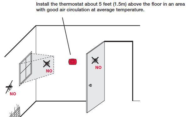
Do not install in locations where the thermostat can be affected by
- Drafts or dead spots behind doors and in corners
- Hot or cold air from ducts
- Sunlight or radiant heat from appliances
- Concealed pipes or chimneys
- Unheated/uncooled areas such as an outside wall behind the thermostat
Pre-installation checklist
Package contents
Check to make sure your package includes the following items: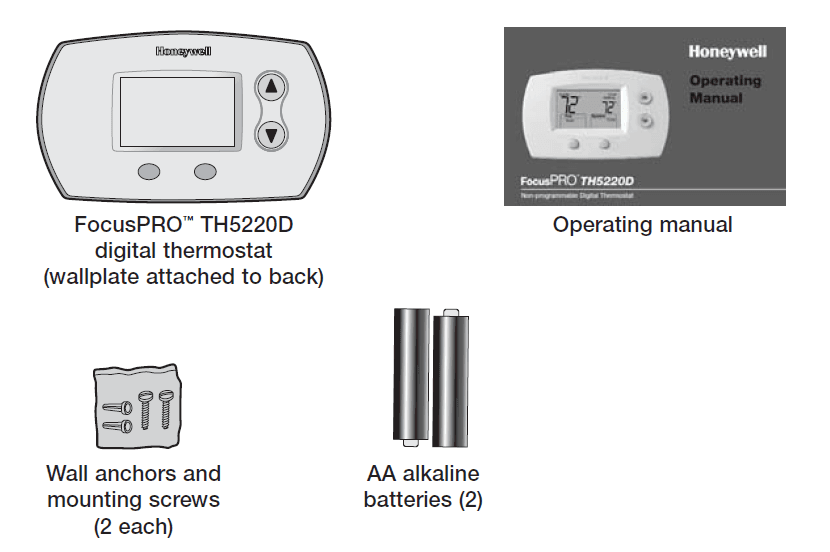
Required tools & supplies
- No. 2 Phillips screwdriver
- Small pocket screwdriver
- Drill
- Drill bit (3/16” for drywall, 7/32” for plaster)
- Hammer
- Pencil
- Electrical tape
- Level (optional)
Wallplate installation
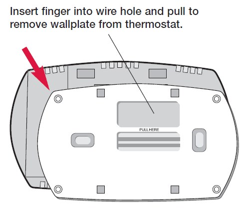
Remove the wallplate from the thermostat as shown at left, then follow directions below for mounting.
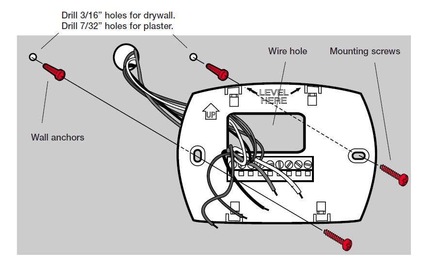
- Pull wires through wire hole.
- Position wallplate on wall, level and mark hole positions with pencil.
- Drill holes at marked positions as shown below, then tap in supplied wall anchors.
- Place wallplate over anchors, insert and tighten mounting screws.
Wiring
CAUTION: ELECTRICAL HAZARD. Can cause electrical shock or equipment damage. Disconnect power before wiring.
Wiring
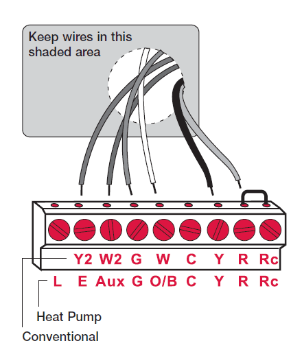
- Loosen screw terminals, insert wires into terminal block, then re-tighten screws.
- Push excess wire back into the wall opening. Keep wires in shaded area as shown at left.
- Plug the wall opening with nonflammable insulation to prevent drafts from affecting thermostat operation.
Terminal Designations
Conventional Terminal Letters:
- Y2 2nd stage compressor contactor
- W2 2nd stage heat relay
- G Fan relay
- W 1st stage heat relay
- C Common wire from the secondary side of the cooling system transformer
- Y 1st stage compressor contactor
- R Heating power. Connect to a secondary side of the heating system transformer.
- Rc Cooling power. Connect to a secondary side of the cooling system transformer.
Heat Pump Terminal Letters:
- L Heat pump reset. L terminal powered continuously when System is set to Em Heat.
- E Emergency heat relay Aux Auxiliary heat relay
- G Fan relay
- O/B Changeover valve for heat pumps
- C Common wire from the secondary side of the cooling system transformer.
- Y Compressor contactor
- R Heating power. Connect to the secondary side of the heating system transformer.
- Rc Cooling power. Connect to the secondary side of the cooling system transformer.
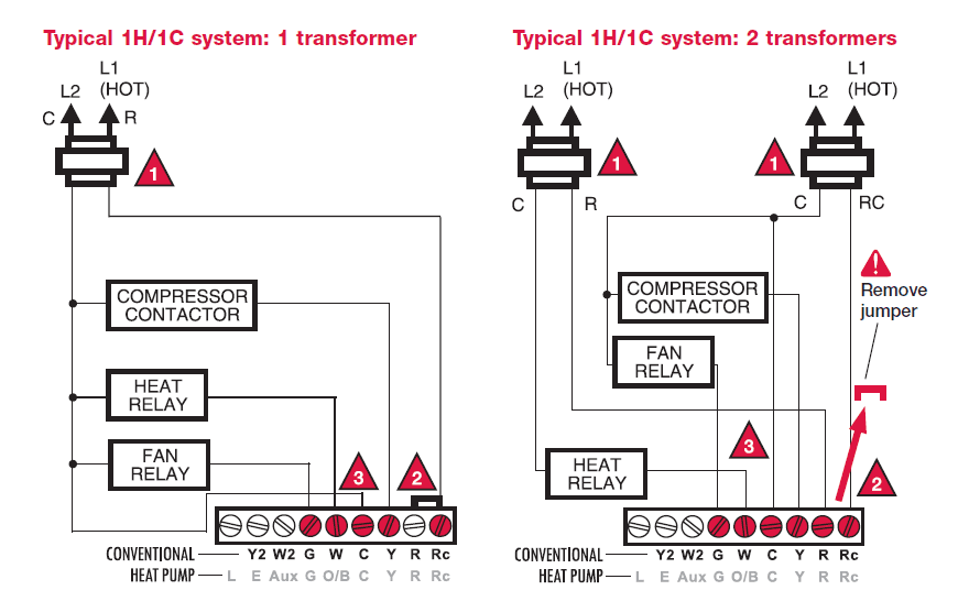
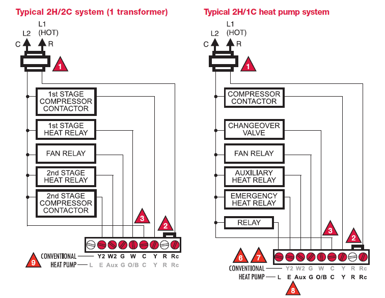
Wiring diagrams
- Power supply. Provide disconnect means and overload protection as required.
- Factory-installed jumper. Remove for 2-transformer systems only.
- Optional 24VAC common connection.
- In Installer Setup, set the system type to Heat Only.
- In Installer Setup, set system type to 1Heat/1Cool Heat Pump & changeover valve to 0 or B.
- In Installer Setup, set the system type to 2Heat/1Cool Heat Pump.
- L terminal is powered continuously when the thermostat is set to Em Heat.
- Install field jumper between Aux and E if there is no emergency heat relay.
- In Installer Setup, set the system type to 2Heat/2Cool conventional.
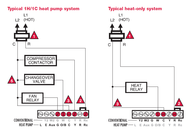
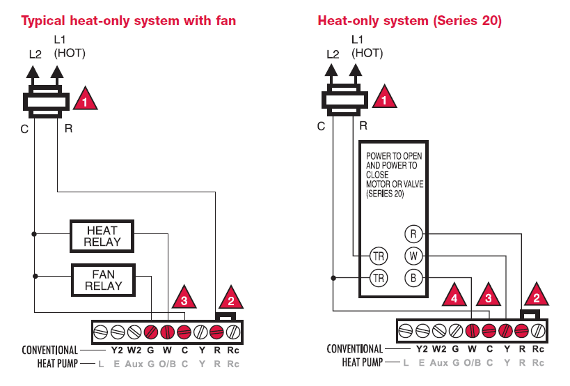
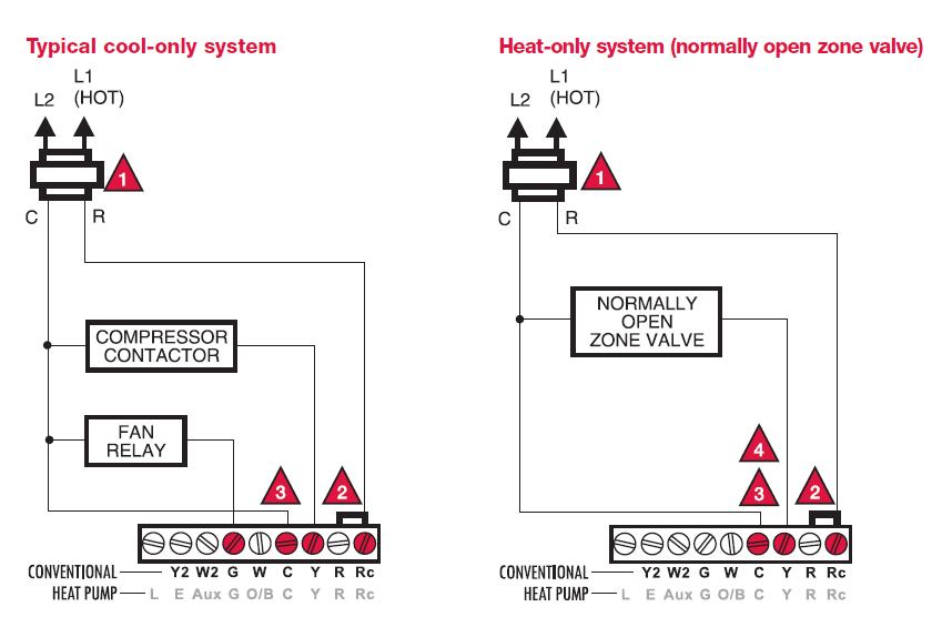
- Power supply. Provide disconnect means and overload protection as required.
- Factory-installed jumper. Remove for 2-transformer systems only.
- Optional 24VAC common connection.
- In Installer Setup, set system type to Heat Only.
- In Installer Setup, set system type to 1Heat/1Cool Heat Pump & changeover valve to 0 or B.
- In Installer Setup, set system type to 2Heat/1Cool Heat Pump.
- L terminal is powered continuously when thermostat is set to Em Heat.
- Install field jumper between Aux and E if there is no emergency heat relay.
- In Installer Setup, set system type to 2Heat/2Cool conventional.
Power options & mounting
AC Power
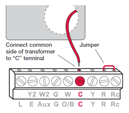
- The thermostat can be powered by 24 VAC power, or by batteries.
- To wire the thermostat for AC power, connect the common side of the cooling transformer to the “C” terminal as shown at left.
- Important: Remove R/Rc jumper for 2-transformer systems only. (See wiring diagram on page 5.)
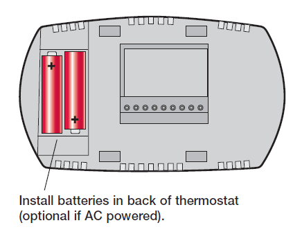
- The thermostat can be powered by batteries alone or, if used with AC power, can provide backup power to the display during power interruptions.
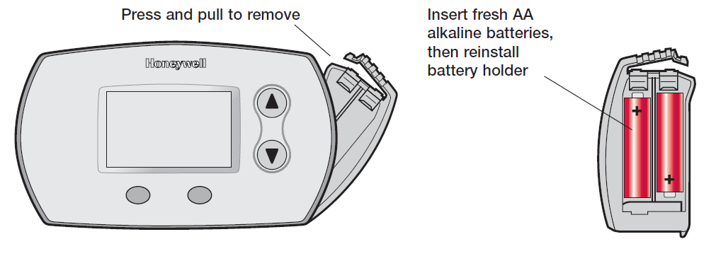
- After installation, batteries can be changed without removing the thermostat from the wall (see page 15).
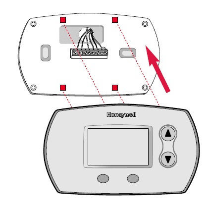
To Mount Thermostat
- Align the 4 tabs on the wallplate with corresponding slots on the back of the thermostat, then push gently until the thermostat snaps in place.
Installer setup
Follow the procedure below to configure the thermostat to match the installed heating/cooling system, and customize feature operation as desired.
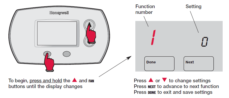
Setup Function
- System type
- Changeover valve (O/B terminal)
- Fan control (heating)
- Heat cycle rate (CPH: cycles/hour)
- Second-stage heat cycle rate/ Auxiliary heat (CPH)
- Emergency heat cycle rate (CPH)
- Compressor cycle rate (CPH)
- Second-stage compressor cycle rate (CPH)
- System setting adjustment
- Temperature display
- Compressor protection
- Auxiliary heat control
- The heat temperature range stops
- The cool temperature range stops
Installer system test
Follow the procedure below to test the heating, cooling and fan.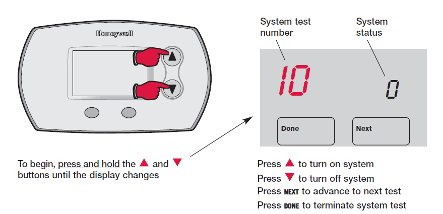
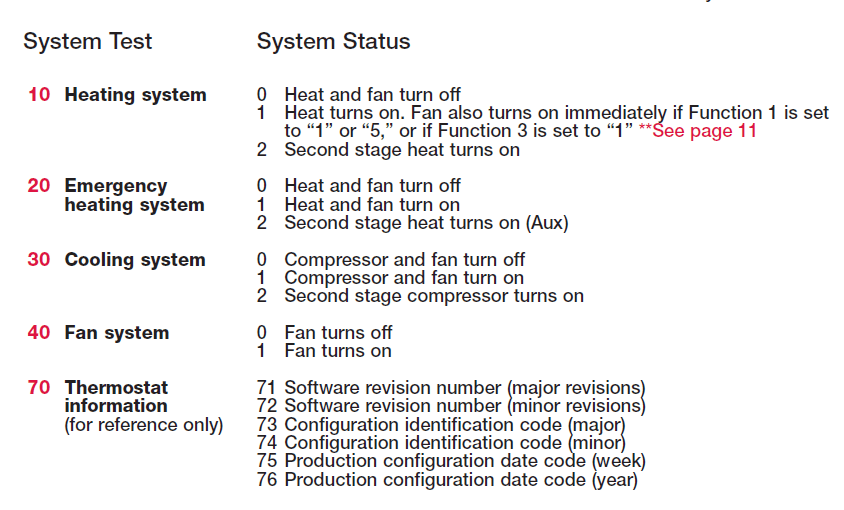
Auto changeover (Setup Function 12)
Auto Changeover is a feature used in climates where both air conditioning and heating are used on the same day. When the system is set to Auto, the thermostat automatically selects heating or cooling depending on the indoor temperature.
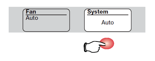
Heat and cool settings must be at least 3 degrees apart. The thermostat will automatically adjust settings to maintain this 3-degree separation (called “deadband”).
The 3-degree separation between heating and cooling set temperatures is fixed, and cannot be changed.
Built-in compressor protection (Setup Function 15)
- This feature helps prevent damage to the compressor in your air conditioning or heat pump system.
- Damage can occur if the compressor is restarted too soon after shutdown. This feature forces the compressor to wait for a few minutes before restarting.
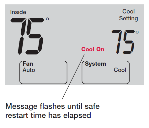
- During the wait time, the message Cool On or Heat On (heat pumps only) will flash on the display .When the safe wait time has elapsed, the message stops flashing and the compressor turns on.
Auxiliary heat control (Setup Function 26)
Systems with heat pumps can be set to operate in one of two ways:
- Comfort Setting: The thermostat will prioritize comfort over economy depending on heat pump performance, load conditions and whether the equipment is calling for heat. Raising the temperature just a few degrees will often activate auxiliary heat.
- Economy Setting: The thermostat will attempt to reach the temperature setting without activating auxiliary heat. The thermostat waits a preset time before allowing auxiliary heat to be activated depending on the compressor stage performance, and on how many degrees the temperature setpoint is changed.
A quick reference to controls
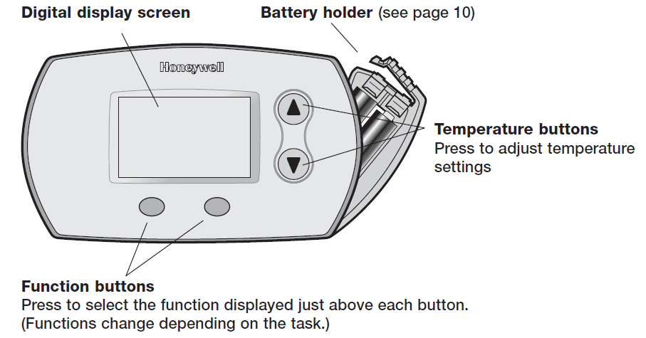
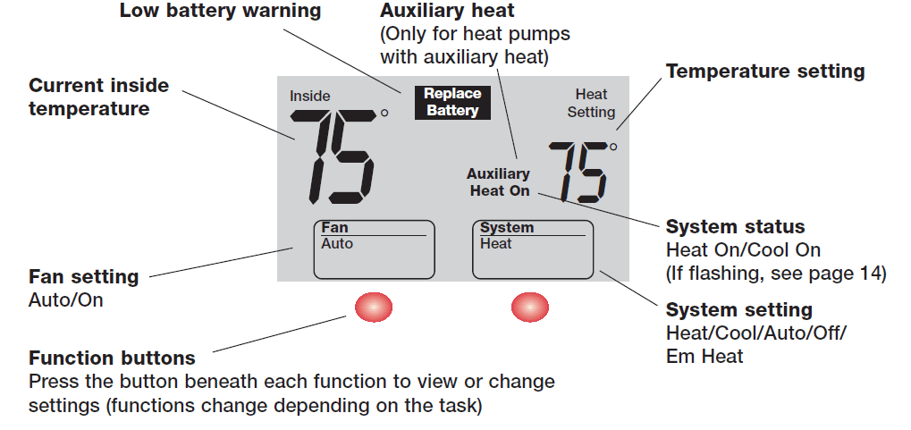
A quick reference to display screen
Battery replacement
For more manuals by Honeywell, visit ManualsLibraryy
Honeywell FocusPRO TH5220D Non-Programmable Digital Thermostat Installation Guide-FAQs
How do I access the installer setup menu?
Press and hold the bottom left button and the Up arrow for 5 seconds. This will open the INSTALLER MENU. Use the arrow buttons to navigate through the options. When “ISU” appears, press SELECT to modify settings.
Will my thermostat work without an internet connection?
Yes, the thermostat will continue to control your heating and cooling system even if Wi-Fi is unavailable. It will maintain the current settings.
How is a digital thermostat powered?
A digital thermostat uses a thermistor to measure electrical resistance and determine indoor temperature. It then adjusts the system based on the preset temperature settings.
Why is the “Heat On” light flashing on my thermostat?
If “Heat On” is flashing or “Wait” appears on the screen, the system is in a delay mode to prevent damage. Wait about 5 minutes for the system to respond. Also, check that the furnace door is securely closed.
What is the compressor cycle rate?
The compressor cycle rate determines how often the system runs within an hour. High-efficiency gas or oil forced-air systems typically have a cycle rate of 3 per hour.
How do I adjust the temperature settings?
Tap the temperature display to adjust the heating or cooling setpoint. Tap again to switch between heating and cooling settings. Press SELECT to confirm, then navigate to DONE and press SELECT to save.
Can I use the thermostat without Wi-Fi?
Yes, the thermostat functions normally without Wi-Fi. It will continue to regulate the temperature based on your last programmed settings.
Is a digital thermostat better than an analog one?
Yes, digital thermostats are more accurate and efficient than analog models. While analog thermostats are cheaper, digital ones provide better temperature control and energy savings.

