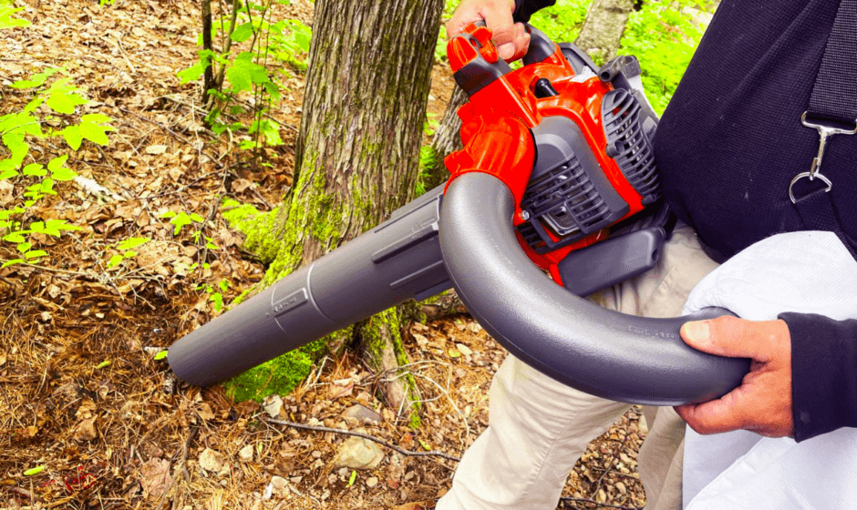
Husqvarna 125BVX Series Gas Leaf Blower
DESCRIPTION
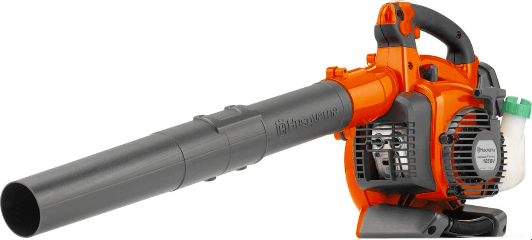
The blower
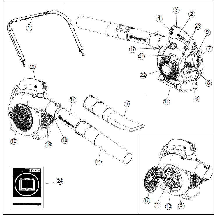
- Shoulder strap (125BVX–SERIES)
- Throttle trigger
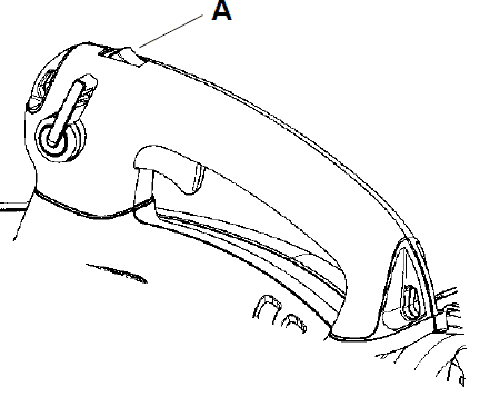
- STOP switch
- Variable speed control (125BX–SERIES and 125BVX–SERIES)
- Fan housing
- Fuel cap
- Air filter
- Choke
- Primer bulb
- Inlet cover
- Vacuum handle
- Cutters (125BX–SERIES and 125BVX–SERIES)
- Fan impeller
- Standard nozzle
- High-velocity nozzle
- Blower tube
- Tube clamp bolt
- Tube clamp nut
- Muffler
- Ground wire
- Starter handle
- Starter device (125BX–SERIES and 125BVX–SERIES)
- Carburetor adjustment screws
- Operator’s manual
Accessories (125BX–SERIES and 125BVX–SERIES)
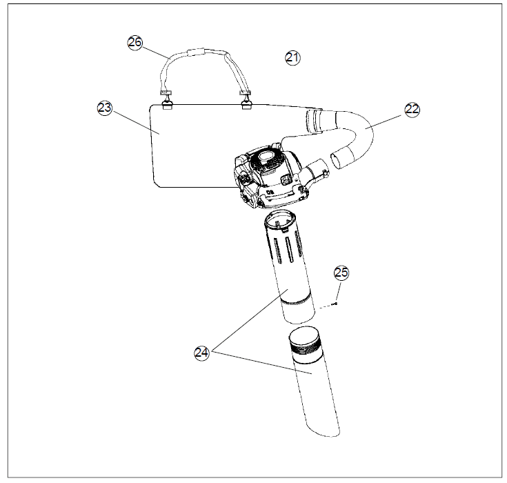
- 21. Vacuum device with collection components consisting of items 22–26 below
- 22. Collection bag tube
- 23. Collection bag
- 24. Vacuum tube in two sections
- 25. Screw
- 26. Shoulder strap
Safety equipment
- The following equipment on the blower is designed to protect personnel and materials. These components should receive special attention whenever you
operate, inspect, and service the blower. - Stop switch
- The stop switch (A) is used to stop the engine.

- Muffler
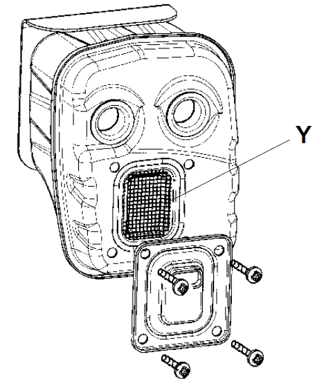
- The muffler is designed to give the lowest possible noise level and to direct the engine’s exhaust fumes away from the operator. Mufflers fitted with catalytic
converters are also designed to reduce harmful exhaust components. - The engine exhaust fumes are hot and can contain sparks, which may cause fire if they come in contact with dry or flammable material.
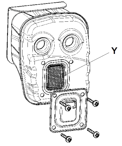
- Some blower models, esp. those sold in countries where the climate is dry, are equipped with a spark-arresting screen (B). This screen must be cleaned or replaced at specific intervals. See the Maintenance section.

- Other equipment
- Throttle trigger
- The speed and the output of the engine are regulated by the throttle trigger (C).
- Variable speed control
- The variable speed control (D) is designed to allow setting engine speed as necessary during blower use only.
- To avoid causing damage to the unit, DO NOT attempt to use the variable speed control during starting or during vacuum use.
- Fan housing
- The blower fan housing (E) and the fan impeller (F) provide high-performance air discharge.
- Inlet cover
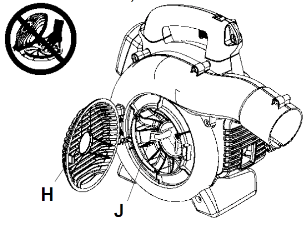
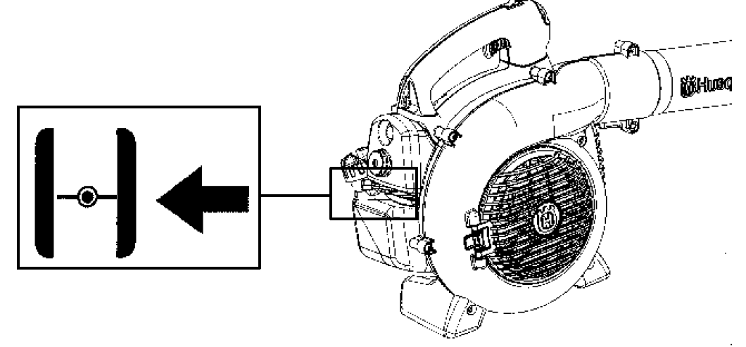
- An inlet cover (H) is located on the side of the fan housing. Opening this cover allows access for cleaning and inspecting the impeller (125BX–SERIES and 125BVX–SERIES only). If the vacuum tube is used, it must be fitted to the opening in the inlet cover. To open the inlet cover, use a tool to lift the edge of the cover opposite the hinge (indicated by the arrow on the inlet cover).

- Cutters
- (125BX–SERIES and 125BVX–SERIES)
- Two cutters (J) are fastened to the impeller. The cutters are there to mulch leaves and other debris that have been vacuumed before they enter the collection bag.
- Blower tube and nozzle
- NOTE: The tube clamp bolt and nut must be installed prior to initial use (see the general description of the blower on page 6).
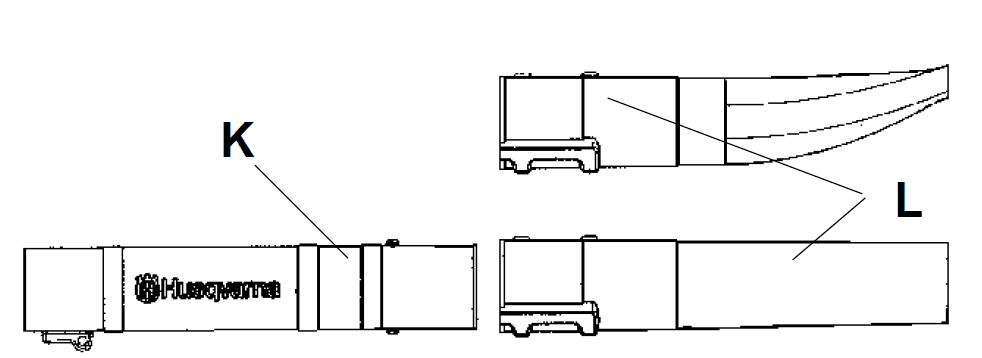
- The blower tube (K) has a pegged slot mounting system to the unit. To install or remove the blower tube (or collection bag tube for the 125BVX–SERIES), the tube clamp bolt must be removed. Align the slot in the blower air outlet with the raised rib on the tube and insert the tube until the holes in the tube and housing align. Re–insert the tube clamp bolt and tighten.

- Starter device and starter handle
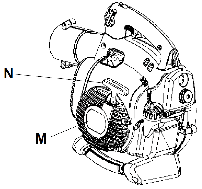
- The starter device (M) is located on the side of the engine shrouding and engages the crankshaft only when the starter handle (N) is pulled.

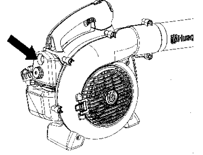
- Fuel cap
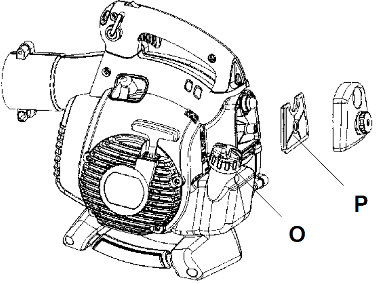
- The fuel cap (O) is located at the rear of the engine shrouding on the fuel tank and has a seal to prevent fuel from leaking out.

- Air filter
- The air filter (P) consists of a fiber filter medium in a resilient frame. The air filter should be cleaned at specific intervals (see Maintenance section). Otherwise,
the blower will consume too much fuel, the performance will be reduced and an oily deposit may form on the spark plug electrodes. - Choke
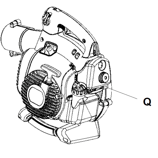
- The choke (Q) is located below the air filter cover and should be used every time the engine is cold–started.

- Adjusting the carburetor
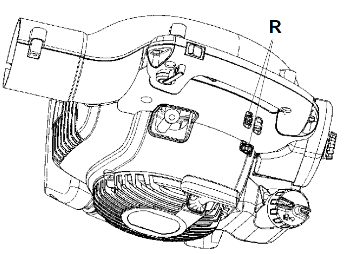
NOT FOR ALL MODELS - There are three adjusting screws (R) for adjusting the carburetor:
- Low speed jet
- High speed jet
- Adjustment screw for idling
- Adjusting the carburetor involves adapting the engine to local operating conditions, e.g. climate, altitude, gasoline and type of two–stroke engine oil used. For
details about carburetor adjustment, see the Maintenance section.
FUEL HANDLING
Fuel mixture
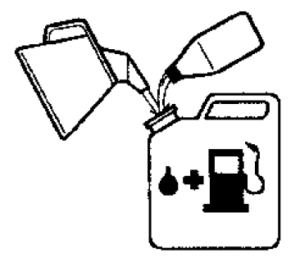
- CAUTION! The machine is equipped with a two–stroke engine and must always be run using a mixture of petrol and two stroke engine oil. It is important to accurately measure the amount of oil to be mixed to ensure that the correct mixture is obtained. When mixing small amounts of fuel, even small inaccuracies can drastically affect the ratio of the mixture.

- The lowest octane recommended is 90. If you run the engine on a lower octane than 90, it can result in knocking. This gives rise to a high engine temperature,
which can result in serious engine damage. - When working at continuous high revs, a higher octane rating is recommended.
- Two–stroke oil
- For best results and performance, use HUSQVARNA two–stroke oil, which is specially formulated for our two–stroke engines. Mixture 1:50 (2%).
- If HUSQVARNA two–stroke oil is not available, you may use another two-stroke oil of good quality that is intended for air cooled engines. Contact your dealer when selecting an oil. Mixing ratio 1:33 (3%).
STARTING AND STOPPING
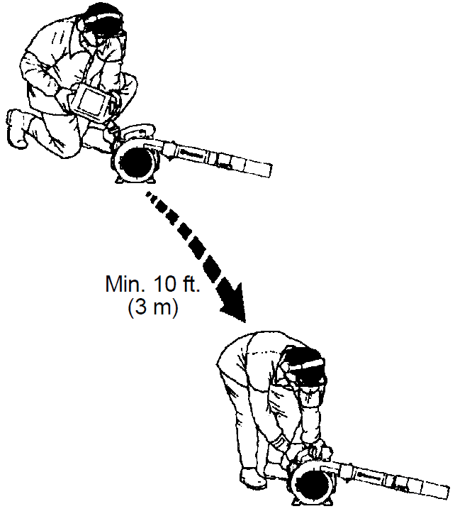
- Clean the area around the fuel cap. Contamination in the tank can cause operating problems.
- Ensure that the fuel is well mixed by shaking the container before filling the tank
Cold engine
- Primer bulb: Press the primer bulb 10 times until fuel begins to fill the bulb. The primer bulb need not be completely filled.

- Choke: Move the blue engine choke lever over to the FULL CHOKE (closed) position

USING THE BLOWER
To blow away debris on the ground
Fitting the blower tube and nozzle on the blower
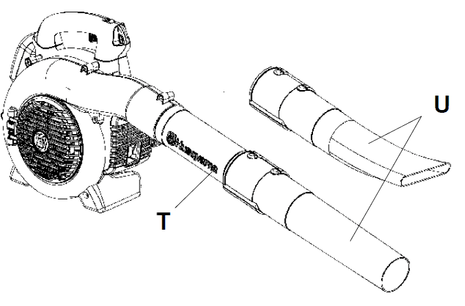
- The blower tube (T) has a pegged slot mounting system to the unit. To install or remove the blower tube (or collection bag tube for 125BVX–SERIES), the tube clamp bolt must be removed. Align slot in the blower air outlet with the raised rib on the tube and insert tube until the holes in the tube and housing align. Re–insert the tube clamp bolt and tighten

- The nozzles (U) have a bayonet mount for connection to the blower tube. Air is channeled through the blower tube to the nozzles, where the air discharge velocity increases and the air stream discharge pattern is formed to provide best performance. The length of the blower tube can be adjusted by twisting the nozzle to the left to disengage the bayonet mount and sliding the nozzle to the appropriate position. Twist the nozzle to the right until a click is felt to resecure the nozzle.
Blowing
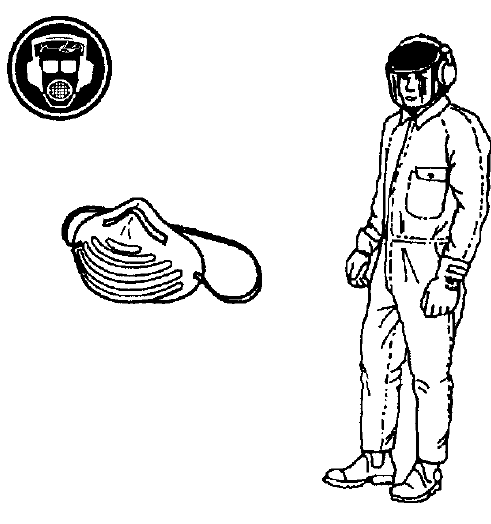
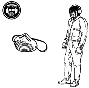
- Before you begin blowing, put on the required safety equipment.

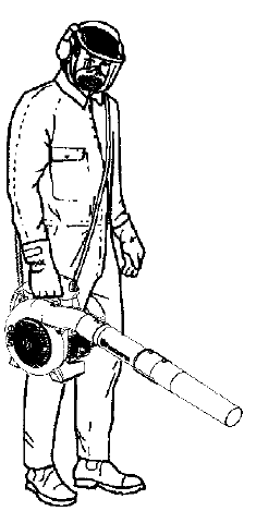
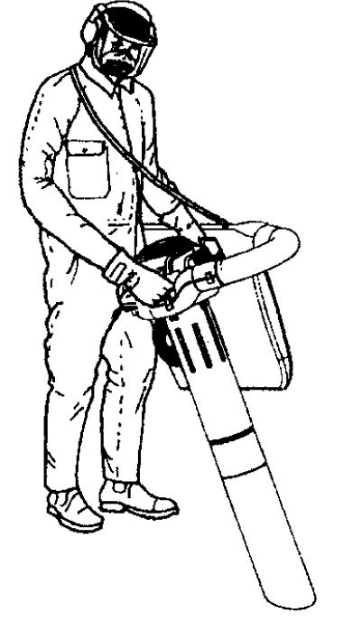
- 125BVX–SERIES can be used with a shoulder strap for extra comfort. The strap should be worn over the shoulder as shown.

Standard nozzle
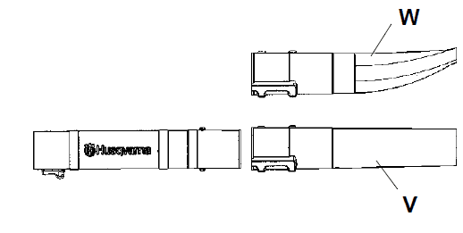
- The standard nozzle (V) is included with the 125B, 125BX–SERIES and 125BVX–SERIES. When greater accuracy and high air stream concentration is desired, use the standard nozzle.

- High–velocity nozzle
- The high–velocity nozzle (W) is an accessory of the blower (included with the 125BX–SERIES and 125BVX–SERIES). When a wider air stream and greater air
velocity is desired, use the high–velocity nozzle.
To vacuum debris from the ground (125BX–SERIES and 125BVX–SERIES)
Fitting the collection bag with the various vacuum tubes The vacuuming device is an accessory (included with the 125BVX–SERIES).
- Open the collection bag. Insert the collection bag tube from inside the bag to fit in the vacuum inlet opening of the bag as shown. Ensure elastic is seated in
groove. Close the zipper on the bag. - Remove the blower tube and install the collection bag tube. Install and tighten tube clamp bolt. Attach the carrying strap to the collection bag loops.
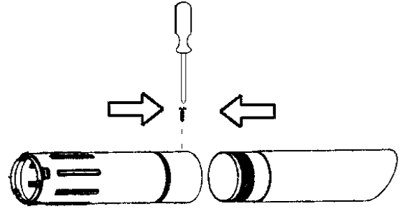
- Align arrows on lower vacuum tube and upper vacuum tube. Push lower vacuum tube into upper vacuum tube until the lower tube is securely seated in the upper tube (about 3 inches/7 cm). Permanently assemble the two tubes together with the supplied screw.

Vacuuming
- Before vacuuming, put on the required safety equipment.

- When operating the blower, the collection bag must be supported by the shoulder strap. The strap should be worn over the shoulder as shown.

MAINTENANCE
Cooling system
The engine is equipped with a cooling system for maintaining the right operating temperature. The cooling system consists of the following components:
- Air intake on the starter device (Z).
- Fan blades on the flywheel (AA).
- Cooling fins on the cylinder (BB).
- Cylinder cowling (guides cooling air flow against cylinder surfaces). Clean the cooling system by brushing once a week, or more often, if necessary. A dirty or blocked cooling system will cause the blower to overheat and this will damage the cylinder and piston.
For more manuals by Huqvarna visit ManualsLibraryy
What is the correct fuel mix ratio for a Husqvarna 125BVX?
The recommended fuel-to-oil mix is 50:1 (2% oil). This means 2.5 fluid ounces of oil per 1 gallon of gas.
Why won’t my Husqvarna leaf blower stay running?
A clogged fuel filter is a common cause. Old fuel can leave behind a sticky residue that blocks the filter, preventing proper fuel flow.
What wind speed does the Husqvarna 125BVX produce?
This blower generates wind speeds up to 170 MPH, with an air volume of 470 CFM and a 12.5 N blowing force for strong clearing performance.
What type of oil should I use in my Husqvarna 125BVX?
For best performance, use Husqvarna two-stroke oil with a 50:1 mix ratio.
How does a leaf blower work?
A motor-driven fan spins to create centrifugal force, pushing air through a nozzle to generate a powerful airflow for clearing leaves and debris.
Why does my leaf blower run for a few minutes and then stop?
A dirty air filter or stale fuel could be restricting airflow or fuel flow to the engine. Regularly clean or replace the air filter and use fresh fuel.
How do I mix fuel for a two-stroke engine?
Mix 50 parts gasoline to 1 part oil (50:1). For every 1 liter of gas, add 20ml of oil.
What is a good wind speed for a leaf blower?
Ideal wind speed ranges from 110 to 200 MPH, depending on your needs. Higher speeds are better for wet leaves and stubborn debris.

