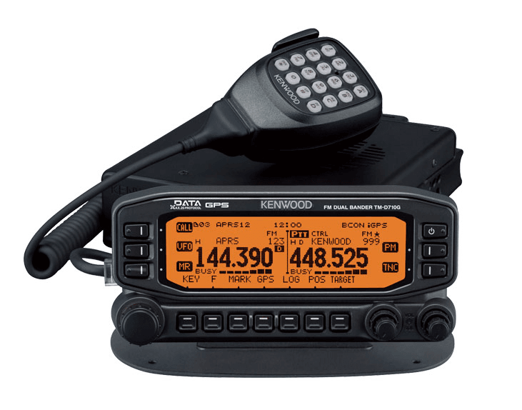
Kenwood TM-D710A APRS Communication Radio
PREPARATION
MOBILE INSTALLATION
TX/ RX Unit Installation
Select a safe, convenient location inside your vehicle that will minimize danger to your passengers and yourself while the vehicle is in motion. Consider installing the transceiver under the dash in front of the passenger seat so that knees or legs will not strike the radio during sudden braking of your vehicle. Try to pick a well-ventilated location that is shielded from direct sunlight.
Note: You may experience interference on your GPS receiver when using in or around 438.8 MHZ (A band) and/or 443.8 MHz (B band). To eliminate the interference, ensure that the transceiver is installed at a location separate from your GPS receiver.
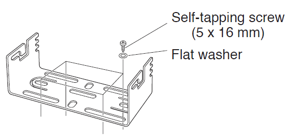
- Install the mounting bracket in the vehicle using the supplied self-tapping screws and flat washers (4 of each are supplied).
- The bracket can be mounted with the bracket opening facing down, for under-dash mounting, or facing up.
- The bracket must be installed so that the 3 screw slots on the edge of each bracket side are facina the back.

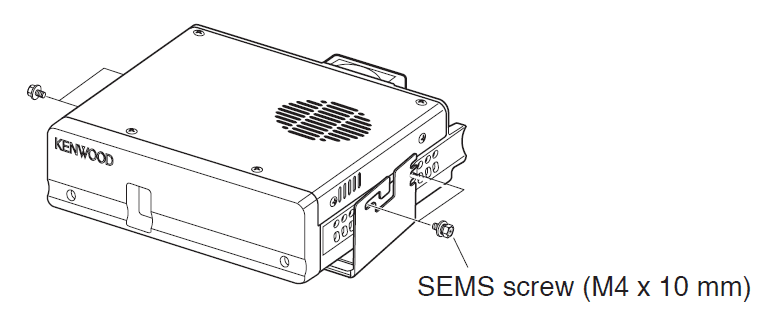
- Position the transceiver, then insert and tighten the supplied hexagon SEMS screws and flat washers (4 of each are supplied, 2 for each side of the bracket).
- Ensure that all hardware is tightened to prevent vehicle vibration from loosening the bracket or TX/ RX unit.

- Set an appropriate angle for the TX/ RX unit, using the 3 screw slots on the rear edge of each bracket side.

- Ensure that all hardware is tightened to prevent vehicle vibration from loosening the bracket or TX/ RX unit.
Operation Panel Installation
- Clean and dry the installation location.
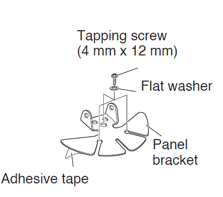
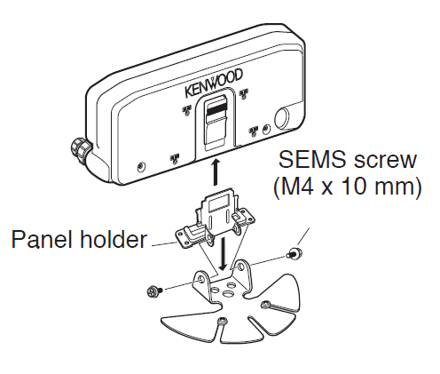
Do not install the bracket close to an airbag. - Remove the release paper from the base of the panel bracket, then secure it in place using the 3 supplied self-tapping screws.
- Allow the panel to set for a while to ensure it remains fast. Otherwise, vibrations may occur.
- After removing the release paper, it cannot be reused.

- Attach the panel holder to the panel bracket using the 2 supplied SEMS screws.
- Attach the operation panel to the panel holder so that it locks in place.

Power Cable Connection
Be sure to use a 12 V vehicle battery that has sufficient current capacity. If the current to the transceiver is insufficient, the display may darken during transmission or the transmit output power may drop excessively. Never connect the transceiver to a 24 V battery.
Note: If you use the transceiver for a long period when the vehicle battery is not fully charged or when the engine is OFF, the battery may become discharged and will not have sufficient reserves to start the vehicle. Avoid using the transceiver under these conditions.
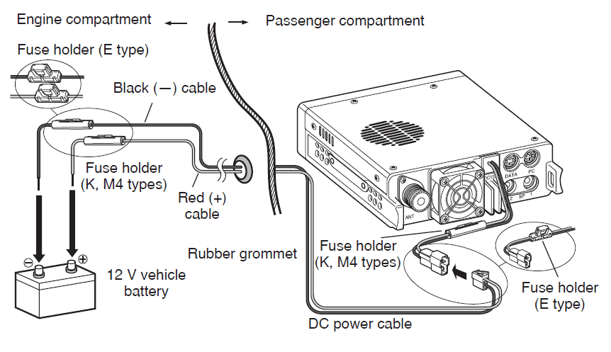
- Route the DC power cable supplied with the transceiver directly to the vehicle’s battery terminals using the shortest path from the transceiver.
- When using a noise filter, it should be installed with an insulator to prevent it from touching metal on the vehicle.
- We do not recommend using a cigarette lighter socket, as some cigarette lighter sockets introduce an unacceptable voltage drop.
- If the power cable must be routed through a hole in the vehicle chassis or body, for example, in the firewall at the front of the passenger compartment, use a rubber grommet to protect the cable from abrasion. Dismantle the fuse holder to pass the cable through the firewall.
- The entire length of the cable must be dressed so it is isolated from heat, moisture, and the engine secondary (high voltage) ignition system/ cables.
- After the cable is in place, wind heat-resistant tape around the fuse holder to protect it from moisture. Tie down the full run of cable.
- To prevent the risk of short circuits, disconnect other wiring from the negative (–) battery terminal before connecting the transceiver.
Fixed Station
Operation Panel Installation
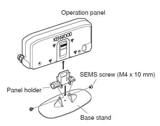
- Attach the panel holder to the base stand using the 2 supplied SEMS screws.
- Attach the operation panel to the panel holder so that it locks in place.

Power Cable Connection
In order to use this transceiver for fixed station operation, you will need a separate 13.8 V DC power supply that must be purchased separately. The recommended current capacity of the power supply is 13 A.
Note: Do not plug the DC power supply into an AC outlet until you make all connections.
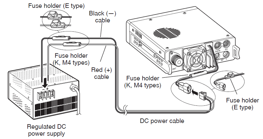
- Ensure that the transceiver and DC power supply are both OFF.
- Connect the DC power cable to the regulated DC power supply and ensure that the polarities are correct (Red: positive, Black: negative).
- Use the supplied DC power cable to connect the transceiver to a regulated power supply. Do not directly connect the transceiver to an AC outlet.
- Do not substitute the cable with smaller-gauge wires.
- Connect the DC power cable to the transceiver.
- Press the connectors firmly together until the locking tab clicks.
Note: For your transceiver to fully exhibit its performance capabilities, we recommend using an optional PS-33 (20.5 A, 25% duty cycle) power supply.
Replacing Fuses
If the fuse blows, determine the cause, then correct the problem. After the problem is resolved, replace the fuse. If newly installed fuses continue to blow, disconnect the power cable and contact your authorized Kenwood dealer or an authorized Kenwood service center for assistance.

Caution: Only use fuses of the specified type and rating; otherwise, the transceiver could be damaged.

Operation Panel and Microphone Connection
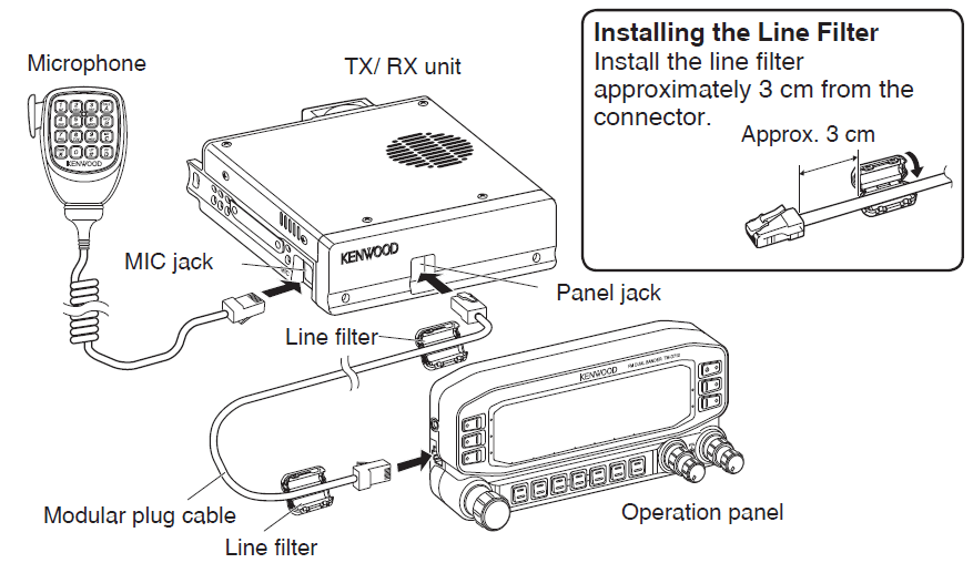
Plug the microphone plug into the MIC jack, then connect the Operation panel to the TX/ RX unit with the supplied cable.
- Attach the microphone hanger to an appropriate position using the screws included in the screw set.
Antenna Connection
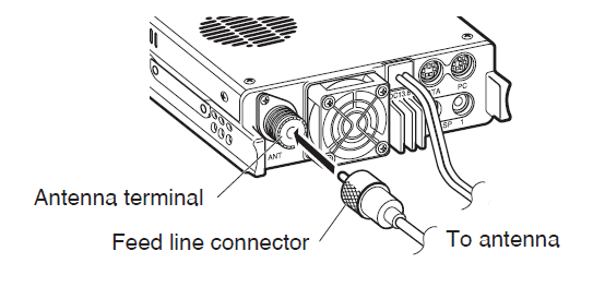
Before operating, you must first install an efficient, well-tuned antenna. The success of your installation will depend largely on the type of antenna and its correct installation. The transceiver can give excellent results if the antenna system and its installation are given careful attention.
Use a low-loss coaxial feed line that also has a characteristic impedance of 50 Ω to match the transceiver input impedance. Coupling the antenna to the transceiver via feed lines having an impedance other than 50 Ω reduces the efficiency of the antenna system and can cause interference to nearby broadcast television receivers, radio receivers, and other electronic equipment.
Caution:
- Transmitting without first connecting an antenna or other matched load may damage the transceiver. Always connect the antenna to the transceiver before transmitting.
- All fixed stations should be equipped with a lightning arrester to reduce the risk of fire, electric shock, and/or transceiver damage.
Accessory Connections
External Speakers
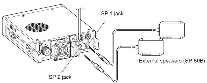
If you plan to use external speakers, choose speakers with an impedance of 8 Ω. The external speaker jacks accept a 3.5 mm (1/8”) mono (2-conductor) plug. We recommend using SP-50B speakers.
There are 2 speaker jacks on the rear of the transceiver: SP 1 and SP 2.
MAINTENANCE
GENERAL INFORMATION
This product has been factory aligned and tested to specification before shipment. Attempting service or alignment without factory authorization can void the product warranty.
SERVICE
When returning this product to your dealer or service center for repair, pack it in its original box and packing material. Include a full description of the problem(s) experienced. Include your telephone number along with your name and address in case the service technician needs to contact you; if available, also include your fax number and e-mail address. Don’t return accessory items unless you feel they are directly related to the service problem.
You may return this product for service to the authorized Kenwood dealer from whom you purchased it, or any authorized Kenwood service center. Please do not send subassemblies or printed circuit boards; send the complete product. A copy of the service report will be returned with the product.
SERVICE NOTE
If you desire to correspond on a technical or operational problem, please make your note legible, short, complete, and to the point. Help us help you by providing the following:
- Model and serial number of the equipment
- Question or problem you are having
- Other equipment in your station about the problem
CAUTION: Do not pack the equipment in crushed newspapers for shipment! Extensive damage may result from rough handling or shipping.
Note:
- Record the date of purchase, serial number, and the dealer from whom this product was purchased.
- For your information, retain a written record of any maintenance performed on this product.
- When claiming warranty service, please include a photocopy of the bill of sale or other proof of purchase showing the date of sale.
CLEANING
To clean the case of this product, use a neutral detergent (no strong chemicals) and a damp cloth.
TROUBLESHOOTING
The problems described in this table are commonly encountered operational malfunctions and are usually not caused by circuit failure.
The transceiver will not power up after connecting a 13.8 V DC power supply and pressing [ ]. Nothing appears on the display.
Probable Cause:
- The power cable was connected backwards.
- One or more of the power cable fuses are open.
Corrective Action:
- Connect the supplied DC power cable correctly (red to + terminal and black to – terminal).
- Look for the cause of the blown fuse(s). After inspecting and correcting any problems, install a new fuse(s) with the same ratings.
The frequency cannot be selected by turning the Tuning control or by pressing the microphone [UP]/[DWN].
Probable Cause:
Memory Recall was selected.
Corrective Action:
Press [VFO].
Most keys and the Tuning control do not function.
Probable Cause:
- One of the Lock functions is ON.
- The transceiver is in Channel Display mode.
Corrective Action:
- Unlock all of the Lock functions.
- With the transceiver power OFF, press [LOW] + Power ON to exit Channel Display mode.
Memory channels cannot be selected by turning the Tuning control or by pressing the microphone [UP]/[DWN].
Probable Cause:
No data has been stored in any Memory channel.
Corrective Action:
Store data in some Memory channels.
You cannot transmit even though you are pressing [PTT].
Probable Cause:
- The microphone plug was not inserted completely into the transceiver.
- You selected a transmit offset that places the transmit frequency outside the allowable range.
- The external TNC is transmitting.
Corrective Action:
- Switch the power OFF, then insert the microphone plug until the locking tab clicks in place.
- Turn the offset shift function OFF.
- Press [PTT] after the TNC has finished transmitting.
“MCP ERR” appears on the display. (MCP-2A communications error)
Probable Cause:
- Ensure that the connection between the TM-D710 and the PC is correct.
- While performing a large amount of processing on the PC.
- EchoLink mode turns ON.
- There are other reasons why communication was not possible.
Corrective Action:
- Checking connection
- Shut down other software that you may be running.
- Turn EchoLink mode OFF.
- Turn the TM-D710 power source OFF and ON, one time.
SPECIFICATIONS
Specifications are subject to change without notice due to advancements in technology.
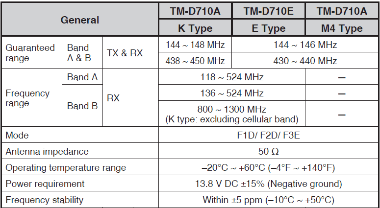
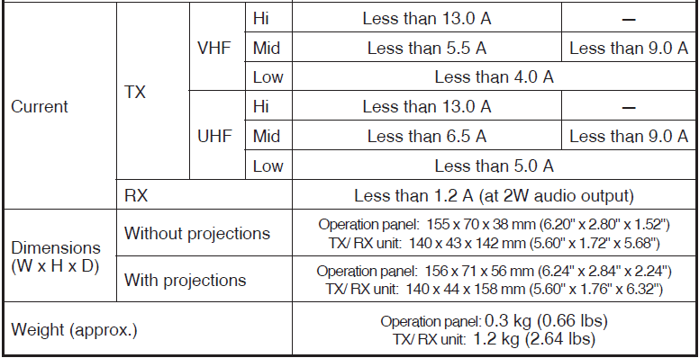
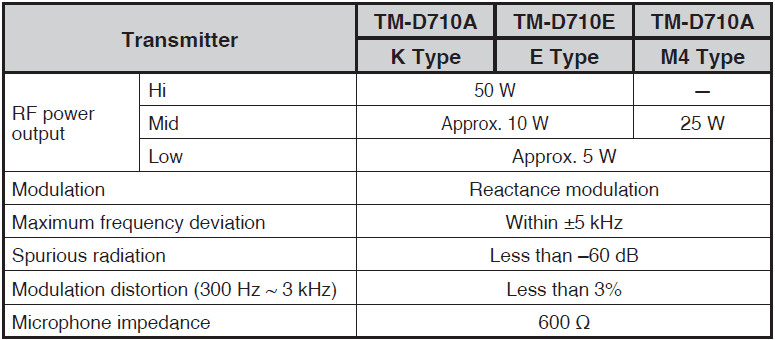
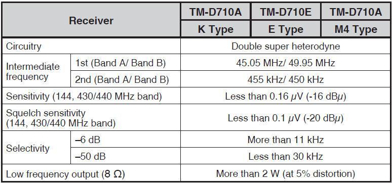
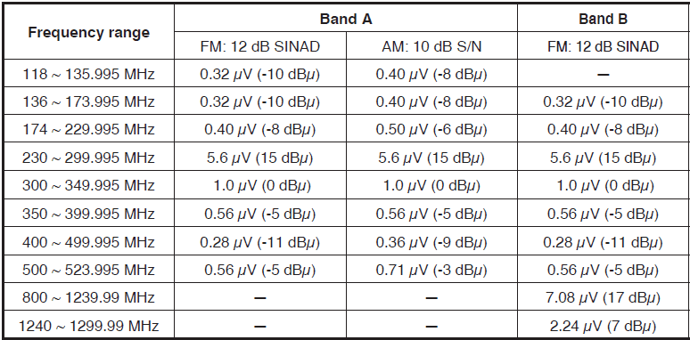
Sensitivity (approx.) <excluding 144, 430/440 MHz band>
For more manuals by Kenwood, visit ManualsLibrary
Kenwood TM-D710A APRS Communication Radio- FAQs
What is APRS and how does the TM-D710A use it?
APRS (Automatic Packet Reporting System) allows real-time data sharing such as GPS location, messages, and weather reports. The TM-D710A supports APRS with built-in TNC and GPS connectivity, enabling location tracking and communication with other APRS users.
How do I program memory channels on the TM-D710A?
Use the front panel controls to select a frequency, then hold the “MR” or “Memory Write” button to store it. You can label and organize frequencies for quick access.
How do I adjust power output levels?
Press the “FUNC” key followed by the power setting button (often labeled “PWR”). Choose from low, medium, or high power depending on your range and battery needs.
Can I use the TM-D710A as a cross-band repeater?
Yes, the TM-D710A supports cross-band repeater mode. Activate it through the menu settings by enabling cross-band repeat and setting both A and B bands to the desired frequencies.
How do I reset the TM-D710A to factory settings?
To reset, turn off the unit, then press and hold the “A” and “B” band buttons while turning the power back on. Follow the on-screen prompts to complete the reset.
What kind of GPS units are compatible with the TM-D710A?
The TM-D710A supports NMEA 0183-compatible GPS units. It can receive and transmit position data for APRS use when a compatible GPS receiver is connected.
How can I update the firmware of the TM-D710A?
Firmware updates can be downloaded from Kenwood’s official website. Connect the radio to your PC using a compatible programming cable, then follow the provided update instructions carefully.
What does the TNC do in this radio?
The built-in TNC (Terminal Node Controller) manages packet data for APRS communication. It enables transmission and reception of APRS messages and location beacons without the need for a separate external device.

