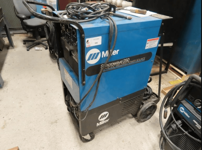
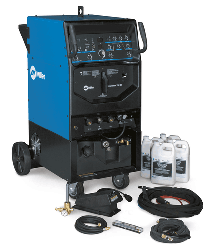
Miller Electric Syncrowave 250 Welder
SAFETY PRECAUTIONS FOR SERVICING
Servicing Hazards
ELECTRIC SHOCK can kill.
- Do not touch live electrical parts.
- Stop the engine or turn OFF the welding power source and wire feeder, and disconnect and lockout the input power using the line disconnect switch, circuit breakers, or by removing the plug from the receptacle before servicing unless the procedure specifically requires an energized unit.
- Insulate yourself from the ground by standing or working on dry insulating mats big enough to prevent contact with the ground.
- Do not leave the live unit unattended.
- When testing a live unit, use the one-hand method. Do not put both hands inside unit. Keep one hand free.
- Disconnect input power conductors from the deenergized supply line BEFORE moving a welding power source.
SIGNIFICANT DC VOLTAGE exists after the removal of input power on inverters. - Turn off the inverter, disconnect the input power, and discharge input capacitors according to instructions in the Maintenance Section before touching any parts.
STATIC ELECTRICITY can damage parts on circuit boards.
- Put on a grounded wrist strap BEFORE handling boards or parts.
- Use proper static-proof bags to store, move, or ship PC boards.
FIRE OR EXPLOSION can result from placing the unit on, over, or near combustible surfaces.
- Do not place the unit on, over, or near combustible surfaces.
- Do not service the unit near flammables.
FLYING PIECES OF METAL or DIRT can injure eyes.
- Wear safety glasses with side shields or a face shield during servicing.
- Be careful not to short metal tools, parts, or wires together during testing and servicing.
HOT PARTS can cause severe burns.
- Do not touch hot parts bare-handed.
- Allow a cooling period before servicing the welding gun or torch.
EXPLODING PARTS can cause injury.
- Failed parts can explode or cause other parts to explode when power is applied to inverters.
- Always wear a face shield and long sleeves when servicing inverters.
ELECTRIC SHOCK HAZARD from incorrect use of test equipment.
- Turn off the welding power source and wire feeder or stop the engine before making or changing meter lead connections.
- At least one meter lead should be a self-retaining spring clip, such as an alligator clamp.
- Read the instructions for the test equipment.
HIGH-FREQUENCY RADIATION can interfere with radio navigation, safety services, computers, and communications equipment.
- Have only qualified persons familiar with electronic equipment perform this installation.
- The user is responsible for having a qualified electrician promptly correct any interference problem resulting from the installation.
- If notified by the FCC about interference, stop using the equipment at once.
- Have the installation regularly checked and maintained.
- Keep high-frequency source doors and panels tightly shut, keep spark gaps at the correct setting, and use grounding and shielding to minimize the possibility of interference.
DEFINITIONS
Warning Label Definitions
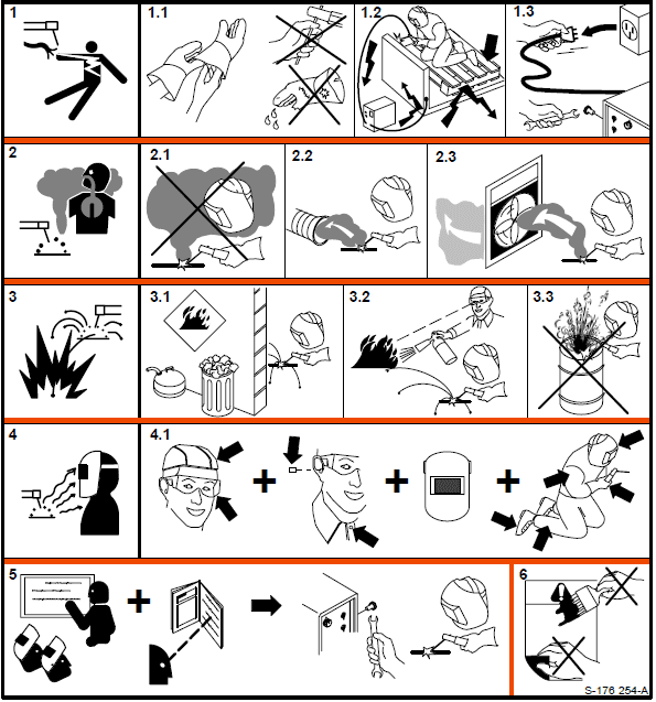
- An electric shock from a welding electrode or wiring can kill.
- 1.1 Wear dry insulating gloves. Do not touch the electrode with your bare hand. Do not wear wet or damaged gloves.
- 1.2 Protect yourself from electric shock by insulating yourself from the work and ground.
- 1.3 Disconnect the input plug or power before working on the machine.
- Breathing welding fumes can be hazardous to your health.
- 2.1 Keep your head out of the fumes.
- 2.2 Use forced ventilation or local exhaust to remove the fumes.
- 2.3 Use a ventilating fan to remove fumes.
- Welding sparks can cause an explosion or fire.
- 3.1 Keep flammables away from welding. Don’t weld near flammable.
- 3.2 Welding sparks can cause fires. Have a fire extinguisher nearby and have a watch person ready to use it.
- 3.3 Do not weld on drums or any closed containers.
- Arc rays can burn eyes and injure skin.
- 4.1 Wear a hat and safety glasses. Use ear protection and a button shirt collar. Use a welding
helmet with the correct shade of filter. Wear complete body protection.
- 4.1 Wear a hat and safety glasses. Use ear protection and a button shirt collar. Use a welding
- Become trained and read the instructions before working on the machine or welding.
- Do not remove or paint over (cover) the label.
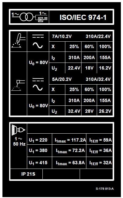
Rating Label For CE Products
INSTALLATION
Specifications
|
Rated Welding Output |
PFC** | Amperes Input at AC Balanced Rated Load Output, 50/60 Hz, Single-Phase |
KVA |
KW |
Amp Range |
Max OCV |
IP Rating | |||
| 200 V | 230 V | 460 V | 575 V | |||||||
| NEMA Class II (40) – 250 Amperes, 30 Volts AC, 40% Duty Cycle | No PFC | 106 (4.6*) | 92 (4*) | 46 (2*) | 37 (1.6*) | 21 (0.89*) | 11.4 (0.68*) |
5–310 A |
80 V |
21 |
| With PFC | 76 | 66 | 33 | 26 | 15.2 | 11.4 | ||||
| *While idling **Power Factor Correction | ||||||||||
|
Rated Welding Output |
PFC ** | Amperes Input at AC Balanced Rated Load Output, 50/60 Hz, Single-Phase |
KVA |
KW |
Amp Range |
Max OCV |
IP Rating | ||||||||
| 200 V | 220 V | 230 V | 260 V | 380 V | 415 V | 460 V | 520 V | 575 V | |||||||
| NEMA Class I (60) – 200 | No PFC | 85 (4.6*) | 77 (4.2*) | 74 (4*) | 65 (3.5*) | 45 (2.4*) | 41 (2.2*) | 37 (2*) | 33 (1.8*) | 30 (1.6*) | 17 (0.9*) | 8.3 (0.7*) | |||
| Amperes, 28 Volts AC, 60% Duty Cycle | 5–310 A | 80 V | 21 | ||||||||||||
| With PFC | 55 (57*) | 64 (51*) | 48 (49*) | 48 (49*) | 37 (30*) | 34 (27*) | 24 (25*) | 48 (49*) | 19 (20*) | 11 (11*) | 8.3 (0.6*) | ||||
| *While idling **Power Factor Correction | |||||||||||||||
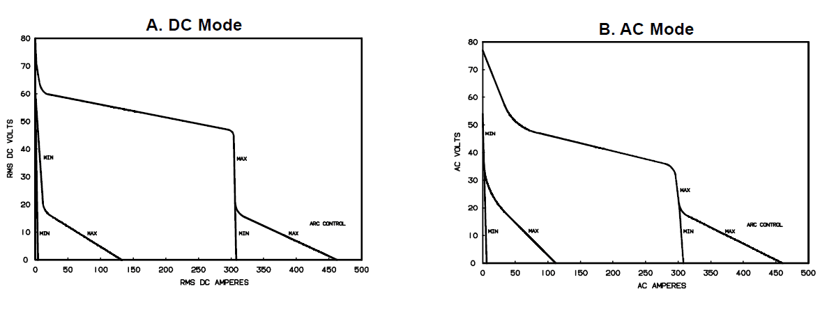
Volt-Ampere Curves
The volt-ampere curves show the minimum and maximum voltage and amperage output capabilities of the welding power source. Curves of other settings fall between the curves shown.
Duty Cycle And Overheating
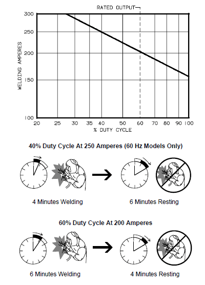
Duty Cycle is the percentage of 10 minutes that a unit can weld at the rated load without overheating. If the unit overheats, the thermostat opens, the output stops, the light goes on (CE models only), and the cooling fan runs. Wait fifteen minutes for the unit to cool. Reduce amperage or duty cycle before welding.
- Exceeding the duty cycle can damage the unit and void the warranty.
Overheating

Selecting A Location
Movement
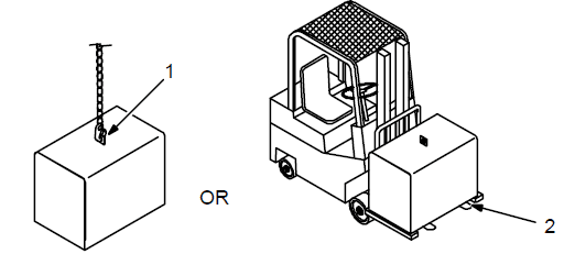
- Lifting Eye
- Lifting Forks
Use lifting eyes or lifting forks to move the unit. If using lifting forks, extend the forks beyond the opposite side of the unit. - Rating Label (Non CE Models Only)
- rating Label (CE Models Only, See Section 2-2)
Use the rating label to determine input power needs. The CE label is located on the rear panel. - Plate Label (CE Models Only)
- Line Disconnect Device
Locate the unit near the correct input power supply.
- Special installation may be required where gasoline or volatile liquids are present – see NEC Article 511 or CEC Section 20.
Location And Airflow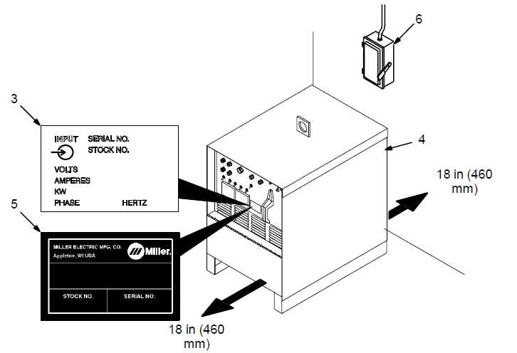
Dimensions And Weights
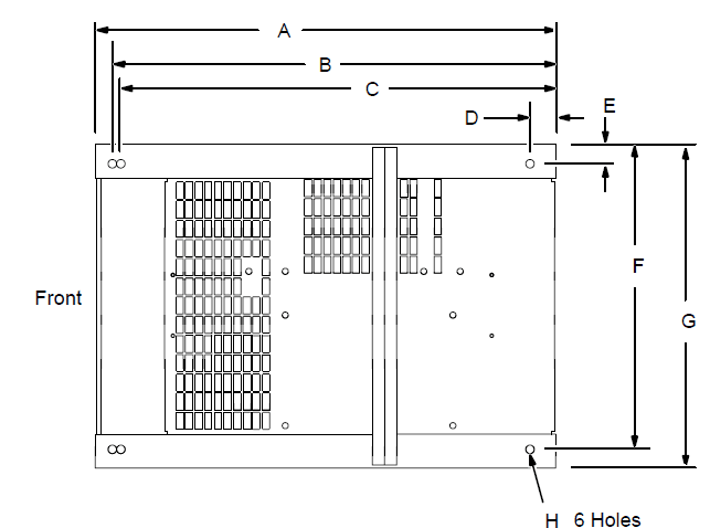
| Dimensions | |||||||||
| Height | 30-3/4 in (781 mm) | ||||||||
| Width | 19-3/4 in (502 mm) | ||||||||
| Length | 27-1/2 in (698 mm) | ||||||||
| A | 27 in (686 mm) | ||||||||
|
| B | 26 in (661 mm) | |||||||
| C | 25-1/4 in (642 mm) | ||||||||
| D | 1-1/2 in (38 mm) | ||||||||
| E | 1-1/8 (29 mm) | ||||||||
| F | 17-7/8 (454 mm) | ||||||||
| G | 19-1/4 (489 mm) | ||||||||
| H | 1/2 in (13 mm) Dia | ||||||||
| Weight | |||||||||
| 355 lbs (161 kg) | |||||||||
Tipping
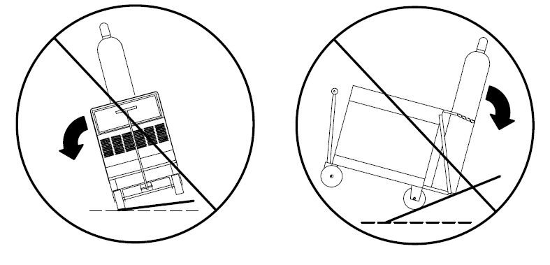
- Be careful when placing or moving unit over uneven surfaces.
Weld Output Terminals And Selecting Cable Sizes
Weld Output Terminals |
Welding Amperes | Total Cable (Copper) Length In Weld Circuit Not Exceeding | |||||||
| 100 ft (30 m) Or Less | 150 ft (45 m) | 200 ft (60 m) | 250 ft (70 m) | 300 ft (90 m) | 350 ft (105 m) | 400 ft (120 m) | |||
| 10 – 60% Duty Cycle | 60 – 100% Duty Cycle | 10 – 100% Duty Cycle | |||||||
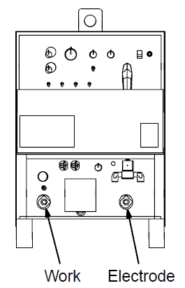
Work Electrode ST-154 795-C | 100 | 4 | 4 | 4 | 3 | 2 | 1 | 1/0 | 1/0 |
| 150 | 3 | 3 | 2 | 1 | 1/0 | 2/0 | 3/0 | 3/0 | |
| 200 | 3 | 2 | 1 | 1/0 | 2/0 | 3/0 | 4/0 | 4/0 | |
| 250 | 2 | 1 | 1/0 | 2/0 | 3/0 | 4/0 | 2-2/0 | 2-2/0 | |
| 300 | 1 | 1/0 | 2/0 | 3/0 | 4/0 | 2-2/0 | 2-3/0 | 2-3/0 | |
| 350 | 1/0 | 2/0 | 3/0 | 4/0 | 2-2/0 | 2-3/0 | 2-3/0 | 2-4/0 | |
| 400 | 1/0 | 2/0 | 3/0 | 4/0 | 2-2/0 | 2-3/0 | 2-4/0 | 2-4/0 | |
| 500 | 2/0 | 3/0 | 4/0 | 2-2/0 | 2-3/0 | 2-4/0 | 3-3/0 | 3-3/0 | |
| Weld cable size (AWG) is based on either a 4-volt or less drop or a current density of at least 300 circular mils per ampere. Contact your distributor for the mm2 equivalent weld cable sizes. S-0007-E | |||||||||
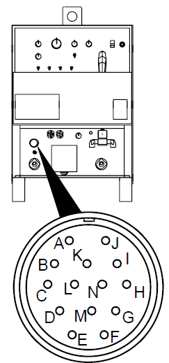
Remote 14 Receptacle
|
| | Socket* | Socket Information |
| | A | 24 volts AC. | |
| B | Contact closure to A completes 24 24-volt AC contactor control circuit. | ||
|
| C | Command reference: 0 to +10 volts DC output to the remote control. | |
| D | The remote control circuit is common. | ||
| E | 0 to +10 volts DC input command signal from the remote control. | ||
| K | Chassis common. | ||
| *The remaining sockets are not used. | |||
115 Volts AC Duplex Receptacle And Shielding Gas Connections
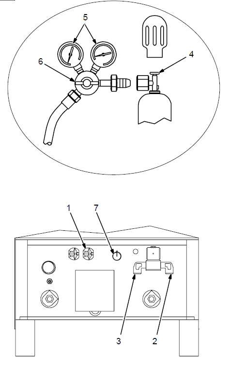
- Turn off the power before connecting to the receptacle.
- 115 V AC Receptacle
Receptacle is protected from overload by circuit breaker CB1 (see Section 7-2). - Gas Valve In Fitting
- Gas Valve Out Fitting
Fittings have 5/8-18 right-hand threads - Cylinder Valve
Open the valve slightly so gas flow blows dirt from the valve. Close the valve. - Regulator/Flow Gauge
- Flow Adjust
Typical flow rate is 20 cfh (cubic feet per hour) (9.4 L/min) - High Frequency Control (see Section 4-1)
Electrical Service Guide
| 60 Hertz Models | Without Power Factor Correction | With Power Factor Correction | ||||||
| Input Voltage | 200 | 230 | 460 | 575 | 200 | 230 | 460 | 575 |
| Input Amperes At Rated Output | 85 | 74 | 37 | 30 | 55 | 48 | 24 | 19 |
| Max Recommended Standard Fuse Or Circuit Breaker Rating In Amperes | 125 | 110 | 60 | 45 | 80 | 70 | 35 | 30 |
| Min Input Conductor Size In AWG/Kcmil | 4 | 6 | 10 | 10 | 8 | 8 | 12 | 14 |
| Max Recommended Input Conductor Length In Feet (Meters) | 173 (53) | 158 (48) | 291 (89) | 455 (139) | 86 (26) | 114 (35) | 186 (58) | 189 (48) |
| Min Grounding Conductor Size In AWG/Kcmil | 6 | 6 | 10 | 10 | 8 | 8 | 12 | 14 |
| Reference: 1996 National Electrical Code (NEC) S-0092-J | ||||||||
| 50 Hertz Models | Without Power Factor Correction | With Power Factor Correction | ||||||
| Input Voltage | 220 | 260 | 380 | 415 | 520 | 220 | 380 | 415 |
| Input Amperes At Rated Output | 77 | 65 | 45 | 41 | 33 | 64 | 37 | 34 |
| Max Recommended Standard Fuse Or Circuit Breaker Rating In Amperes | 125 | 100 | 70 | 60 | 50 | 90 | 60 | 50 |
| Min Input Conductor Size In AWG/Kcmil | 6 | 6 | 8 | 8 | 10 | 6 | 10 | 10 |
| Max Recommended Input Conductor Length In Feet (Meters) | 145 (44) | 202 (62) | 291 (89) | 347 (106) | 372 (113) | 145 (44) | 291 (89) | 347 (106) |
| Min Grounding Conductor Size In AWG/Kcmil | 6 | 8 | 8 | 10 | 10 | 6 | 8 | 10 |
| Reference: 1996 National Electrical Code (NEC) S-0092-J | ||||||||
OPERATION
- Ammeter
See Section 4-3. - Voltmeter
See Section 4-3. - High Frequency Switch
See Section 4-11. - Output (Contactor) Switch
See Section 4-8. - Spot Time Switch And Control
(Optional) See Section 4-5. - Preflow Time Control (Optional)
See Section 4-12. - AC Balance Control
See Section 4-6. - Crater Time Control And Switch
See Section 4-4. - Amperage Adjustment Control And
Switch See Section 4-7. - Arc Force (Dig) Switch And Control
See Section 4-9. - Postflow Time Control
See Section 4-10. - High Temperature Shutdown Light
(CE Models Only)
Lights when the unit overheats and shuts down (see Section 3-3). - Power Switch And Pilot Light
Use a switch to turn the unit and light on and off. - Output Selector Switch
See Section 4-2. - High Frequency Control
See Section 4-11.
Output Selector Switch
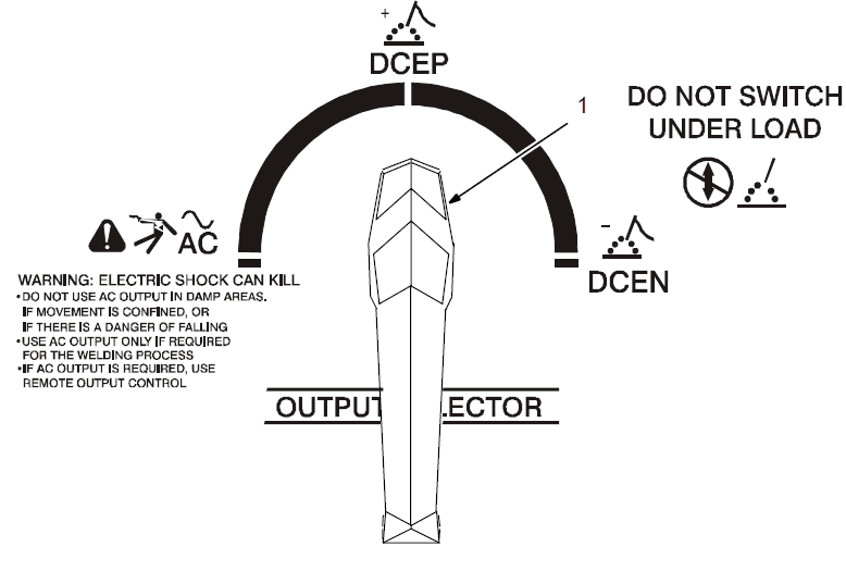
- Output Selector Switch
- Do not use the AC output in damp areas, if movement is confined, or if there is danger of falling. Use the AC output ONLY if required for the welding process, and then use a remote control.
- Do not change the position of the switch while welding or while under load.
Use the switch to select (DCEN) Direct Current Electrode Negative, AC, or (DCEP) Direct Current Electrode Positive output without changing weld output cable connections.
Meters
- Voltmeter
A voltmeter displays voltage at the weld output terminals, but not necessarily the welding arc due to cable resistance, poor connections, etc. - Ammeter
An ammeter displays the weld amperage output of unit.
THEORY OF OPERATION
- Input Terminal Board TE1
Provides means for operation on different input voltages. - Power Switch S1
Provide on/off control of the unit. - Fan Motor FM
Provides cooling of internal components. - Main Transformer T1
Supplies power to the weld output circuit, various control circuits, the main control board PC1, and the fan motor FM. - Control Board PC1
Controls weld output by changing the SCR gate pulses (conduction times) after comparing current
feedback to the selected amperage signal. Also provides input connections for switches S3, S5, S6, and S7. - Arc Control Switch S6 And Control R2
R2 selects short-circuit amperage when S6 is On, and High Frequency control R13 is Off. - Crater Time Switch S7 And Control R11
R11 selects the crater time when S7 is on, and the Amperage Control switch S5 is in the Panel position. - Thermostat TP1
If T1 overheats, TP1 opens, stopping all weld output. - Output (Contactor) Switch S3
Selects on or remote contactor control. - AC Balance Control R3
Controls changes to ac output square wave. - Ammeter A1 And Voltmeter V1
Display weld amperage and voltage while welding. - Amperage Control Switch S5 And Adjustment Control R1
R1 selects the weld output amperage when S5 is in the Panel. - Remote 14 Filter Board
PC2/Remote 14 Receptacle RC1
PC2 protects the unit from high frequency, and RC1 connects the remote amperage and contactor controls to a power source. - Circuit Breaker CB1
Protects a 115-volt AC duplex receptacle RC2 from overload. - 15 115 Volts AC Duplex Receptacle RC2
Provides a connection point for auxiliary equipment. - Postflow Timer TD1
Controls shielding gas and coolant postflow time. - Gas Valve GS1
Provides shielding gas during the weld cycle. - Preflow Timer TD3, Control R12, And Switch S9
R12 selects the time shielding gas flows before the arc starts. S9 is an integral part of R12, so that when R12
is turned past zero (0), TD3 is off. - Spot Timer TD2, Switch S8, And Control R10
R10 selects the time output is available when spot welding. S8 selects off or spot welding with remote contactor control. - High Frequency Transformer T2
Steps up input voltage and charges capacitor C4. - Spark Gaps G And High Frequency Coupling Coil T3
G provides path for C4 to discharge into T3. T3 supplies high-frequency to welding circuit. - High Frequency Intensity Control R13
Changes the amount of HF energy used to start and maintain the arc. - Main Rectifier SR1
Changes the AC output from T1 to full-wave rectified dc. - Background Power Source
Provides reduced weld output ripple at low weld output levels. - Stabilizer Z1
Smooths the DC welding current. - Hall Device HD1
Provides a current feedback signal to PC1 through line filter FL1. - Line Filter FL1
Filters the current feedback signal. - Output Selector Switch S4
Provides either AC or DC and output polarity. - Integrated Rectifier SR2
Provides dc voltage feedback to PC1. - Electrode And Work Weld Output Terminals
Provide weld output.
TROUBLESHOOTING
| |
| Trouble | Remedy |
| Prior to Serial No. KG164875, no weld output; unit completely inoperative – Effective with Serial No. KG164875, no weld output; unit completely inoperative; PL2 off. | Be sure the line disconnect switch is in the On position. |
| Replace building line fuse(s) or reset circuit breaker(s) if open. | |
| Check for proper electrical input connections (see Section 3-11). | |
| Check for proper jumper link position (see Section 3-11). | |
| Check the Power switch S1 and replace if necessary. | |
| Prior to Serial No. KG164875, no weld output; fan runs – Effective with Serial No. KG164875, no weld output; fan runs; PL2 on. | If using the remote control, place Output (Contactor) switch S3 in Remote 14 position, and connect the remote control to Remote 14 receptacle RC1 (see Sections 3-8 and Section 4-8). If the remote is not being used, place Output switch S3 in the On position. |
| Check, repair or replace the remote control device. | |
| Allow a cooling period of approximately 15 minutes. If the thermostat TP1 remains open, check continuity and replace if necessary (see Section 3-3). | |
| Check circuit breaker CB1, and reset if open (see Section 7-2). | |
| Place the Output Selector switch S4 in the desired position (see Section 4-2). | |
| Check the optional preflow timer board TD3, and replace if necessary. | |
| Check the optional spot timer relay TD2 for proper connections and resistance. Replace TD2 if necessary. | |
| Check the continuity of Spot Time switch S8. Check the condition of the contacts. Repair or replace S8 if necessary. | |
| Check SR1, and replace necessary components. If components are replaced, check capacitors C7 through C10. Replace capacitor(s) if necessary. | |
| Check the control board PC1 and connections, and replace if necessary. | |
| Effective with Serial No. KB110695, check resistance and connections of HD1; HD1 is 1600 ohms ±10% between pins 1 and 3 of plug PLG3. Check input and output voltages. Replace HD1 if necessary. | |
| The unit provides only a minimum weld output. | Check the position of the Amperage Control switch S5 (see Section 4-7). |
| Increase the Amperage Adjustment control R1 setting if a remote control is used (see Section 4-7). | |
| Check, repair, or replace the remote control device. | |
| Check resistance and connections of the Amperage Adjustment control R1; R1 is 1000 ohms ±10%. Replace R1 if necessary. | |
| Check SCRs in main rectifier SR1, and replace if necessary. If any SCRs are replaced, check capacitors C7 through C10 for a short or open, and check for proper connections. Replace C7 through C10 if necessary. | |
| Check the control board PC1 and connections, and replace if necessary. | |
| Effective with Serial No. KB110695, check resistance and connections of HD1; HD1 is 1600 ohms ±10% between pins 1 and 3 of plug PLG3. Check input and output voltages. Replace HD1 if necessary. | |
| The unit provides only maximum weld output. | Check the Amperage Adjustment control R1 for proper connections and resistance; R1 is 1000 ohms ±10%. Replace R1 if necessary. |
| Effective with Serial No. KB110695, check resistance and connections of HD1; HD1 is 1600 ohms ±10% between pins 1 and 3 of plug PLG3. Check input and output voltages. Replace HD1 if necessary. | |
| Check connections for continuity to the shunt device on units with Serial No. prior to KB110695. | |
| Check bypass capacitors C13, C14, C16, C17, C18, and C19 for broken leads, shorts, and leakage. Replace if necessary. | |
| Trouble | Remedy |
| Check SCRs in main rectifier SR1, and replace if necessary. If any SCRs are replaced, check capacitors C7 through C10 for a short or open, and check for proper connections. Replace C7 through C10 if necessary. | |
| Check the control board PC1 and connections, and replace if necessary. | |
| Check connections to the line filter FL1. Check the input to PC1. Replace FL1 if necessary. | |
| Erratic weld output. | Check for poor or improper input or output connections. See Sections 3-11 and 3-8. |
| Replace the electrode. | |
| Check the torch assembly, and replace if necessary. | |
| Check fuse F2 in the rectifier SR3 circuit, and replace if necessary. | |
| If the Amperage Control switch S5 is in the Remote position, check, repair, or replace the remote amperage control device if necessary. | |
| Check connections for continuity to the shunt device on units with Serial No. prior to KB110695. | |
| Check the Amperage Adjustment control R1 for proper connections and resistance; R1 is 1000 ohms ±10%. Replace R1 if necessary. | |
| Check bypass capacitors C13, C14, C16, C17, C18, and C19 for broken leads, shorts, and leakage. Replace if necessary. | |
| Check SCRs in main rectifier SR1, and replace if necessary. If any SCRs are replaced, check capacitors C7 through C10 for a short or open, and check for proper connections. Replace C7 through C10 if necessary. | |
| Check the control board PC1 and connections, and replace if necessary. | |
| No or limited AC balance control. | Check AC Balance control R3 for proper connections and resistance; R3 is 5000 ohms ±10%. Replace R3 if necessary. |
| Check the control board PC1 and connections, and replace if necessary. | |
| Check SCRs in main rectifier SR1, and replace if necessary. If any SCRs are replaced, check capacitors C7 through C10 for a short or open, and check for proper connections. Replace C7 through C10 if necessary. | |
| No crater fill time. | Check the position of the Crater switch S7 (see Section 4-4). |
| Check the position of Crater control R11 (see Section 4-4). | |
| Be sure arc voltage is below 24 volts (see Section 3-2. Volt-Ampere Curves). | |
| Check the position of the Amperage Control switch S5, S5 must be in the Panel position (see Section 4-7). | |
| Check the control board PC1 and connections, and replace if necessary. | |
| Crater fill time too long or does not time out. | Check the position of Crater control R11 (see Section 4-4). |
| Check resistance and connections of Crater control R11; R11 is 5 megohms ±10%. Replace R11 if necessary. | |
| Check the control board PC1 and connections, and replace if necessary. | |
| No arc control. | Place the Arc Control switch S6 in the On position. |
| Place High Frequency switch S2 in the Off position. | |
| Be sure arc voltage is below 24 volts (see Section 3-2. Volt-Ampere Curves). | |
| Check the position of Arc Control R2 (see Section 4-9). | |
| Check fuse F1 in the rectifier SR3 circuit, and replace if necessary. | |
| Check resistance and connections of Arc control R2; R2 is 1000 ohms ±10%. Replace R1 if necessary. | |
| Check the control board PC1 and connections, and replace if necessary. | |
| Lack of high frequency at the tungsten electrode; difficulty in starting an arc. | Use the proper size tungsten for welding applications. |
| Use the shortest possible cables (see Section 3-7). | |
| Check cables and torch for cracked or deteriorated insulation or bad connections. Repair or replace necessary parts. | |
| Be sure to disconnect the SMAW electrode cable from the weld output terminal when GTAW welding. | |
| Decrease the gas flow setting. | |
| Use properly prepared tungsten. | |
| Increase the setting of High Frequency Intensity control R13 (see Section 4-11). | |
| Check spark gaps G and readjust if necessary (see 7-4). |
| Trouble | Remedy |
| No high frequency at spark gaps G. | Check the position of High Frequency switch S2 (see Section 4-11). |
| Place Output (Contactor) switch S3 in Remote position and be sure the remote control is connected to Remote receptacle RC1 (see Section 3-8). | |
| Check circuit breaker CB1, and reset if open (see Section 7-2). | |
| Check fuse F1 in the rectifier SR2 circuit, and replace if necessary. | |
| Check coil voltage and connections of the contactor control relay CR1. Check the continuity of the coil and condition of the contacts. Replace CR1 if necessary. | |
| Check coil voltage and connections of the contactor control relay CR5. Check the continuity of coil and condition of contacts. Replace CR5 if necessary. | |
| Check spark gaps G, and readjust if necessary (see Section 7-4). | |
| Check resistance and connections of High Frequency Intensity control R13; R13 is 1.5 ohms ±10%. Replace R1 if necessary. | |
| Check capacitor C4 for a short or open, and check for proper connections. Replace C4 if necessary. | |
| Check transformer T2 for signs of winding failure. Check continuity across windings, and check for proper connections. Check secondary voltages. Replace T2 if necessary. | |
| Check coupling coil T3 for signs of winding failure. Check continuity across windings, and check for proper connections. Replace T3 if necessary. | |
| Check the control board PC1 and connections, and replace if necessary. | |
| No preflow time (optional). | Place Output (Contactor) switch S3 in Remote position and be sure the remote control is connected to Remote receptacle RC1 (see Section 3-8). |
| Check the position of the Preflow Time control R12. | |
| Check the continuity of the Preflow Time switch S9. Check the condition of the contacts. Repair or replace S9 if necessary. | |
| Remove jumper link 1 on terminal strip 1T. | |
| Check the optional preflow timer board TD3, and replace if necessary. | |
| The optional spot timer relay TD2 does not time out. | Place the Spot Time switch S8 in the On position. |
| Remove jumper link 2 from terminal strip 1T. | |
| Place the Spot Time control R10 in the desired position. | |
| Check coil voltage and connections of the spot timer relay TD2. Check the continuity of the coil and condition of the contacts. Replace TD2 if necessary. | |
| Check coil voltage and connections of control relay CR3. Check the continuity of the coil and the condition of the contacts. Replace CR3 if necessary. | |
| Check coil voltage and connections of control relay CR1. Check continuity of coil and condition of contacts. Replace CR1 if necessary. | |
| Postflow timer does not time out. | Check position of Postflow Time control setting (see Section 4-10). |
| Check Control relay CR5 contacts 2 and 5 for proper operation. Replace CR5 if necessary. | |
| Check coil voltage and connections of gas valve GS1. Check continuity of coils. Replace GS1 if nec- essary. | |
| Check input voltage and connections to Postflow timer board TD1. Check continuity of contacts. Re- place TD1 if necessary. | |
| Check control board PC1 and connections, and replace if necessary. | |
| No postflow time. | Check position of Postflow Time control setting (see Section 4-10). |
| Place Output(Contactor) switch S3 in the Remote position, and connect a remote control to recep- tacle RC1 according to Section 3-8. | |
| Check coil voltage and connections of control relay CR5. Check continuity of coil and condition of contacts. Replace CR5 if necessary. | |
| Check coil voltage and connections of gas valve GS1. Check continuity of coils. Replace GS1 if nec- essary. | |
| Check input voltage and connections to Postflow timer board TD1. Check continuity of contacts. Re- place TD1 if necessary. | |
| Check control board PC1 and connections, and replace if necessary. | |
| No gas flow. | Place Output(Contactor) switch S3 in the Remote position, and connect a remote control to recep- tacle RC1 according to Section 3-8. |
| Check circuit breaker CB1, and reset if open (see Section 7-2). |
| Trouble | Remedy |
| Check Control relay CR2 contacts 4 and 7 for proper operation. Replace CR2 if necessary. | |
| Check coil voltage and connections of gas valve GS1. Check continuity of coils. Replace GS1 if nec- essary. | |
| No power output at 115 volts ac recep- tacle RC1; weld output available. | Check circuit breaker CB1, and reset if open (see Section 7-2). |
| Fan motor FM does not run; weld out- put available. Effective with Serial No. KG164875, unit is equipped with Fan- On-Demand, which only runs when cooling is required. | Check and clear fan blade obstruction. |
| Check coil voltage and connections of fan motor FM, and replace if necessary. | |
| Line fuse opens immediately when solid-state contactor SR1 turns on in DC mode only. | Check diode D1, and replace if necessary. |
| Check SCRs in main rectifier SR1, and replace if necessary. If any SCRs are replaced, Check capac- itors C7 through C10 for a short or open, and check for proper connections. Replace C7 through C10 if necessary. | |
| No control of weld output. | Check position of Amperage Control switch S5 (see Section 4-7). |
| Check resistance and connections of Amperage Adjustment control R1; R1 is 1000 ohms ±10%. Replace R1 if necessary. | |
| Check, repair or replace remote control device. | |
| Effective with Serial No. KB110695, check resistance and connections of HD1; HD1 is 1600 ohms ±10% between pins 1 and 3 of plug PLG3. Check input and output voltages. Replace HD1 if necessary. | |
| Check control board PC1 and connections, and replace if necessary. | |
| Tungsten electrode oxidizing and not remaining bright after conclusion of weld. | Check position of Postflow Time control R12 (see Section 4-10). |
| Check and tighten all gas fittings if necessary. | |
| Increase gas flow setting. | |
| Shield weld zone from drafts. | |
| Properly prepare tungsten. | |
| Place High Frequency switch S2 in Start or Continuous position. | |
| Wandering arc – poor control of direc- tion of arc. | Use proper size tungsten for welding application. |
| Properly prepare tungsten. | |
| Controls connected to the Remote 14 receptacle RC1 do not work properly. | Check, repair or replace the remote control device. |
| Check the Amperage Control switch S5 position (see Section 4-7). Check and replace S5 if necessary. | |
| Check Output (Contactor) switch S3 position (see Section 4-8). Check and replace S3 if necessary. | |
| Check the position of jumper links 1 and 2 on terminal strip 1T according to Section 6-2. | |
| Check coil voltage and connections of control relay CR2. Check the continuity of the coil and the condition of the contacts. Replace CR2 if necessary. | |
| Prior to Serial No. KF959379, check choke RFC1 connections. Check the continuity of RFC1. Replace if necessary. Effective with Serial No. KF959379 check remote 14 filter board PC2 (see Section 6-6). Replace PC2 if necessary. | |
| Check the control board PC1 and connections, and replace if necessary. | |
| Ammeter A1 is not displaying the correct weld output amperage. | Calibrate the ammeter as instructed in Section 6-8. |
| Check ammeter A1 voltage; +1 millivolts dc per 3 ampere of weld output. Replace A1 if necessary. | |
| Check the control board PC1 and connections, and replace if necessary. | |
| Effective with Serial No. KB110695, check resistance and connections of hall device HD1; HD1 is 1600 ohms ±10% between pins 1 and 3 of plug PLG3. Check input and output voltages. Replace HD1 if necessary. | |
| Voltmeter V1 is not displaying the correct arc voltage. | Check connections for continuity to voltmeter V1. Replace V1 if necessary. |
| The electronic equipment in the welding area is not working properly. | HF interference problem. Check for proper installation, and correct the problem (see Section 8). |
For more manuals by Miller, visit ManualsLibraryy
Miller Electric Syncrowave 250 Welder-FAQs
What is the input voltage for the Miller Syncrowave 250?
The Syncrowave 250 operates on 200/230/460 volts, with current ratings of 105.8/92/46 amps, at 11.4 kW, single phase, and 60 Hz.
Is the Miller Syncrowave an inverter welder?
Some newer Syncrowave models, like the Syncrowave 210, are AC/DC inverter-based TIG welders. The Syncrowave 250 is a conventional transformer-based machine.
What size breaker do I need for a 250-amp welder?
For welders drawing 200 amps or more, a minimum 50-amp breaker is typically required for safe operation.
What is the maximum metal thickness a 250-amp welder can handle?
A 250-amp welder can weld up to 1/2 inch thick steel plates effectively.
What is the input voltage range for Miller welders?
Miller welders, like the Millermatic 211, accept 120–240V single-phase input and offer up to 230 amps output.
What is a Syncrowave welder?
A Syncrowave is a user-friendly TIG/Stick welder designed for better energy efficiency and ease of use. Newer models are up to 33% more efficient than older machines.
Do welding generators use AC or DC power?
Welding generators can produce both AC and DC. DC is preferred for stable arcs and heavy-duty outdoor welding, while AC works well for thinner metals and indoor jobs.
What type of gas does a Miller welder use?
Certain models, like the Miller Bobcat 265 LP, operate exclusively on LP gas (propane). For TIG welding, argon or argon-based gas mixes are commonly used.

