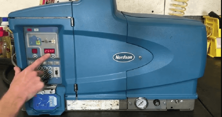
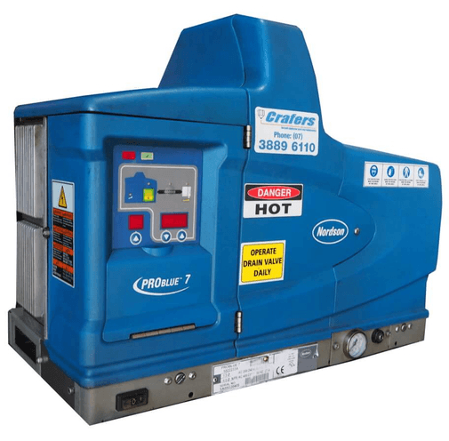
Nordson ProBlue P4 Glue Machine
First Aid
If molten hot melt comes in contact with your skin:
- Do NOT attempt to remove the molten hot melt from your skin.
- Immediately soak the affected area in clean, cold water until the hot melt has cooled.
- Do NOT attempt to remove the solidified hot melt from your skin.
- In case of severe burns, treat for shock.
- Seek expert medical attention immediately. Give the MSDS for the hot melt to the medical personnel providing treatment.
Safety Labels and Tags
Figure 1‐1 illustrates the location of the product safety labels and tags affixed to the equipment. Table 1‐2 provides an illustration of the hazard identification symbols that appear on each safety label and tag, the meaning of the symbol, or the exact wording of any safety message.
The installation kit provided with the melter may contain label overlays that are printed in a variety of languages. If required by governing safety regulations, apply the appropriate overlay to the text portion of the labels shown i Figure 1‐1.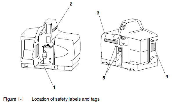 Table 1‐2 General Safety Warnings and Cautions
| Item | Description |
| 1 | WARNING Burn hazard. Hot adhesive. Release pressure before servicing. |
| 2 | CAUTION Burn Hazard. Hot Surfaces. |
| 3 | WARNING Burn hazard. Hot adhesive. Release pressure before servicing. |
| 4 | WARNING Hazardous voltage. Disconnect all power supply connections before servicing. |
| 5 | The symbol means: Hot Surface! Do not touch. |
Key Components
Figure 2‐3 provides the name and the location of key melter components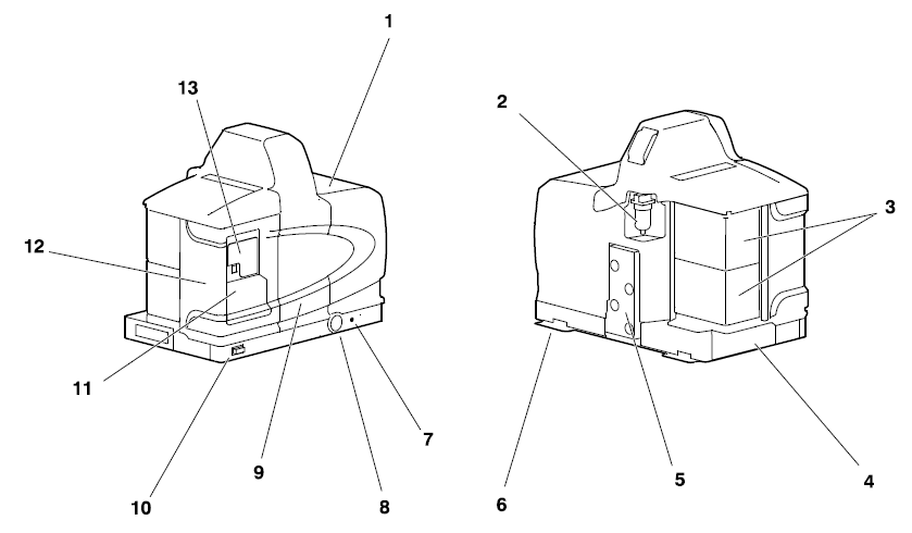
Figure 2-3 Key components
- Tank
- Air filter
- Hose/gun modules
- Chassis
- Manifold
- Sub‐base
- Pressure adjustment screw
- Pressure gauge
- Pump enclosure door
- Control switch
- Keypad door
- Electrical enclosure door
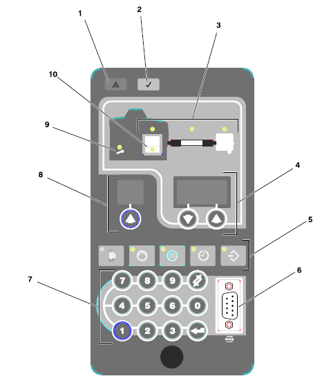
- Control panel (see Figure 2‐4)

Figure 2-4 Control panel
- Fault LED
- Ready LED
- Component keys/LEDs
- Right display and scroll keys
- Function keys
- Serial port
- Keypad
- Left display and scroll key
- Service LED
- Tank low‐level LED
Optional Equipment
The following equipment may be ordered to expand the functionality and capacity of ProBlue adhesive melters.
- Input/output (I/O) expansion cards allow you to expand the available control inputs.
- Communications cards that allow the melter to communicate with other process equipment or a controller that uses standard network protocols.
- Hose/Gun modules allow you to increase the number of hoses/guns connected to the melter.
- Automatic Fill Systems that provide automated transfer of dry adhesive materials to your melter. Choose either the FillEasy® or FillMaster® product.
- 8‐Hose/Gun Expansion Base that expands the capacity of a P10 adhesive melter from 6‐hoses/guns to 8-hoses/guns.
Installation Tasks
The installation sequence is as follows:
- Verify that the required environmental conditions and utilities exist.
- Unpack and inspect the melter.
- Mount the transformer/melter onto the parent machine or support structure.
- Configure the electrical service.
- Connect a compressed air supply.
- Connect hot melt hoses and guns.
- Set up the melter to work with the manufacturing process.
- (Optional) Install inputs and outputs.
- Install optional equipment.
- Connect a gun driver, pattern controller, or timer.
- Flush the melter.
- (Optional) Set up communications between the melter and a PC.
Experience of Installation Personnel
The instructions provided in this section are intended to be used by personnel who have experience in the following subjects:
- Hot melt application processes
- Industrial power and control wiring
- Industrial mechanical installation practices
- Basic process control and instrumentation
Installation Requirements
Before installing the melter, ensure that the desired installation location provides the required clearances, environmental conditions, and utilities.
Clearances
Figure 3‐1 illustrates the minimum clearances that are required between the melter and surrounding objects. Table 3‐1 describes each clearance.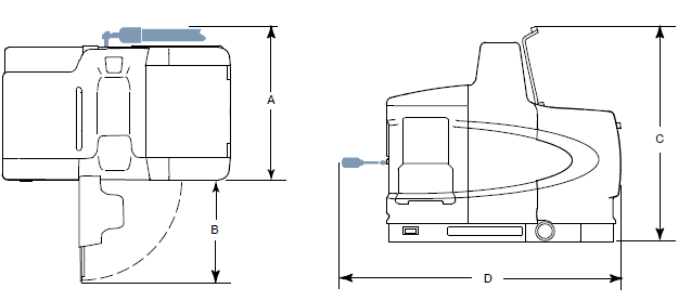 Figure 3‐1 Minimum installation clearances (Top and side views shown
Table 3‐1 Installation Clearances
| Item | Description | Required Clearance |
| A | The distance from the outside edge of a 5/16‐inch Nordson hose to the front face of the melter when a short 90‐degree hose fitting is used to connect the hose to the melter | P4 = 370 mm (14.5 in.) P7 = 370 mm (14.5 in.) P10 = 391 mm (15.4 in.) |
| B | The clearance required to open the pump enclosure door | P4 = 243 mm (9.6 in.) P7 = 243 mm (9.6 in.) P10 = 268 mm (10.55 in.) |
| C | The distance from the melter sub‐base to the front edge of the tank lid when the lid is at its highest point. | P4 = 502 mm (20.0 in.) P7 = 564 mm (22.2 in.) P10 = 656 mm (26.0 in.) |
| D | The clearance required on the left side of the melter to open the electrical enclosure door or remove a hose/gun module. | P4 = 648 mm (25.5 in.) P7 = 711 mm (28.0 in.) P10 = 714 mm (28.1 in.) |
Ventilation
See Figure 3‐2. ProBlue melters are cooled by convection. Air is drawn in through openings in the chassis of the melter and is exhausted out of the ventilation slots at the top of the melter.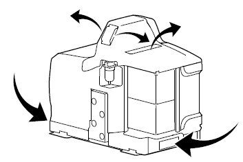 Figure 3‐2 Melter cooling
Electrical Power
Before installing the melter, ensure that the melter will not be overloaded and that the plant’s electrical service is rated to handle the power required by the melter and the hoses and guns that you plan to use. Refer to Appendix A, Calculating Melter Power Requirements, for information about how to calculate the maximum allowable hose lengths and gun wattages that can be used in your manufacturing application.
Compressed Air
To achieve maximum hot melt output, the melter must be connected to an air supply that is capable of providing a maximum of 6.2 Bar (90 psi) of dry, nonlubricated air. The actual pressure required for the melter to support your manufacturing process will depend on such factors as the type of hot melt and gun you are using and the required dimensions of the hot melt bead.
NOTE: The minimum operating air pressure is 0.7 bar (10 psi). Operating the melter with the air pressure set to less than 0.7 bar (10 psi) may cause the pump to function erratically. Nordson recommends that an isolation valve be installed in the plant air supply line just before the melter.
Other Considerations
Consider the following additional factors when evaluating where to install the melter.
- The maximum distance between the melter and each gun is dictated by the power requirement of each hose. Refer to Appendix A, Calculating Melter Power Requirements, for information about how to determine the maximum allowable length.
- The operator must be able to safely reach the control panel and accurately monitor the control panel indicators.
- The operator must be able to safely observe the level of hot melt inside the tank.
- The melter must be installed so that it can be safely removed from its sub‐base.
- The melter must be installed away from areas with strong drafts or where sudden temperature changes occur.
- The melter must be installed where it will be in conformance with the ventilation requirements specified in the Material Safety Data Sheet for the hot melt being used.
- The melter should not be exposed to excessive vibration.
- P4 and P7 melters provide an auxiliary hose port at the bottom of the manifold. If the auxiliary hose port will be used, the parent machine or other support structure must provide clearance under the melter to connect the hose to the auxiliary hose port.
Unpacking the Melter
Before starting the installation, remove the melter from the pallet, locate the installation kit, and inspect the melter for damaged and missing parts. Report any problems to your Nordson representative.
Contents of the Installation Kit
The installation kit provided with the melter contains the components shown in Figure 3‐3. The quantity and type of hose fittings provided in the kit depend upon the melter’s model number and configuration.
Customer‐Supplied Materials
The following additional materials are also required to install the melter.
- A power cable. If the cable clamp that is provided in the installation kit is not used, a rigid or flexible electrical conduit will be required.
- Four 8 mm (5/16 in.) machine bolts with locking hardware
- A plant air supply with an in‐line isolation valve
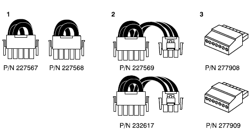
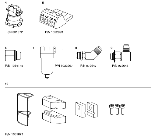
Figure 3‐3 Installation kit components
- Voltage plug (2)
- Voltage plug with neutral (2)
- Input and Output connector (2)
- Cable clamp
- Electrical connector
- NPTF-to-BSPP adapter
- Air filter
- 45-degree hose fitting
- 90-degree hose fitting
- 6-hose manifold guard (P10 only)
Mounting the Melter
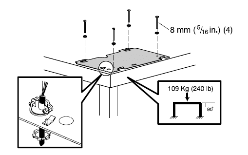
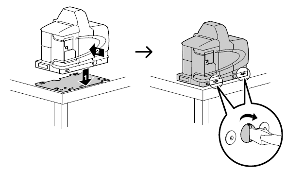
Figure 3‐4 Mounting the sub‐base and the melter
Configuring the Electrical Service
ProBlue melters are shipped from the factory without an attached power cable and an electrical service type specified. To configure the melter to function in your facility, you must connect a power cable and a Nordson-supplied voltage plug to the melter.
To connect a power cable to the melter
- Select a power cable rated for the maximum amperage required by the melter. Ensure that the power cable meets applicable electrical codes and standards. The maximum power draw for each ProBlue shipping configuration, operating at 230 volts, in both 1‐phase and 3‐phase are listed in Table 3‐2. The values presented in Table 3‐2 assume that each hose gun module is being used at its maximum capacity of 2000 watts.
Table 3‐2 Melter Power Requirement
| Melter | Number of Hose/Guns | 1‐Phase Power Draw (Amps) | 3‐Phase Power | |
| Without Neutral | With Neutral | |||
| P4 | 2 | 17 | 15 | 9 |
| 4 | 26 | 23 | 17 | |
| P7 | 2 | 18 | 16 | 10 |
| 4 | 27 | 24 | 17 | |
| P10 | 2 | 18 | 16 | 10 |
| 4 | 27 | 24 | 17 | |
| 6 | 36 | 31 | 18 | |
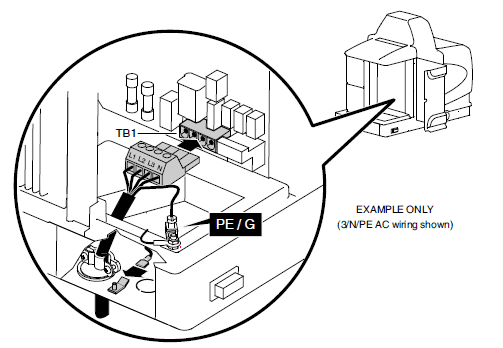
Figure 3‐5 Connecting the power cable, ground lead, and ground jumper
Table 3‐3 Electrical Service Information
| Use Electrical Connector Terminals. |
Use Voltage Plug.. | |||||
| If the Electrical Service Type is. | L1 | L2 | L3 | N | ||
| 400/230 VAC 3‐phase (4‐wire service, including a neutral) See note. | 3/N/PE AC 400/230V | · | · | · | · | 227569 Red/Yellow |
| 230 VAC 1‐phase (2‐wire service, including a neutral) See note. | 1/N/PE AC 200–240V | · | · | 232617 Blue/Yellow | ||
| 200 to 240 VAC 3‐phase (3‐wire service without a neutral) | 3/PE AC 200–240V | · | · | · | 227568 Red/Green | |
| 200 to 240 VAC 1‐phase (2‐wire service without a neutral) | 1/PE AC 200–240V | · | · | 227567 Blue/Green | ||
| NOTE: The 400/230 VAC 3‐phase service (4‐wire service including neutral) includes the 415/240 VAC 3‐phase (4‐wire service, including neutral) voltage. The 230 VAC 1‐phase service (2‐wire service, including a neutral) includes the 240 VAC 1‐phase (2‐wire service, including a neutral) voltage. | ||||||
Table 3‐4 Common Operating Parameters
| Parameter | Parameter Name | Purpose | Default Value |
|
4 |
Ready Delay Time | A timer that delays the activation of the ready LED for a pre‐defined period after the tank, hoses, and guns are at the desired set‐point temperature. The ready delay timer will only activate if the temperature of the tank, at the time the melter is turned on, is below its assigned set‐point temperature by 27 °C (50 °F) or more. |
0 minutes |
|
5 |
Service Interval Time | A timer that turns on a service LED when the value set for the timer equals the number of hours that the heaters have been on. The service LED is used to signal the need for maintenance. |
500 hours |
|
8 |
Automatic Pump On | Determines whether the pump will turn on automatically when all components are at their desired set‐point temperature (enabled) or whether the pump must be turned on manually (disabled). |
Enabled |
| 11 | Create Password | Sets a password that must be entered before any melter operating parameter or set‐point temperature can be changed. | 5000 |
| 20 | Temperature Units | Sets the units of the temperature display to degrees Celsius (C) or degrees Fahrenheit (F). | C |
| 21 | Over Temperature Delta | Sets the number of degrees that any heated component can exceed its assigned set‐point temperature before an over-temperature fault occurs. | 15 °C (25 °F) |
| 22 | Under Temperature Delta | Sets the number of degrees that any heated component can drop below its assigned set‐point temperature before an under-temperature fault occurs. | 25 °C (50 °F) |
| 23 |
Standby Delta | Sets the number of degrees that the temperature of all heated components will be decreased when the melter is placed into standby mode. | 50 °C (100°F) |
| 26 | Manual Standby Time | Sets the amount of time the melter will remain in the standby mode after the standby key is pressed. | Disabled |
|
50 to 77 |
Seven‐day Clock | A group of parameters that control the melter’s clock. The clock is used to automatically turn the heaters on and off and to place the melter into the standby mode. |
Disabled |
Table 3‐5 Parameter Groups
| Group | Parameter Numbers | Group Description |
| Standard | 0 to 11 and 14 | Noneditable and other frequently used parameters |
| Temperature Control | 20 to 26 | Control heaters |
| Input Setup | 30 to 39 | Configure the standard and optional inputs |
| Output Setup | 40 to 46 | Configure the standard and optional outputs |
| Seven-day Clock | 50 to 77 | Configure the clock feature |
Table 3‐6 Operating Parameters
| Parameter | Name | Range of Values | Default Value |
| Standard | |||
| 0 | Enter Password | 0 to 9999 | 4000 |
| 1 | Total Hours with Heaters On (noneditable) | 0-999,999 | 0 |
| 2 | Fault Log (noneditable) | — | _‐F0 (empty) |
| 3 | Change History Log (noneditable) | — | P‐_ (empty) |
| 4 | Ready Delay Time | 0 to 60 minutes | 0 minutes |
| 5 | Service Interval Time | 0 to 8736 hours | 500 hours |
| 6 | Service LED Heater Hours | 0 to 9999 hours | 0 |
| 8 | Automatic Pump On | 0 (disabled) or 1 (enabled) | 1 (enabled) |
| 9 | Automatic Pump On Temperature | 0 (disabled) or (1 to 230 C) | 0 (disabled) |
| 10 | Enable or Disable Password | 0 (disabled) or 1 (enabled) | 0 (disabled) |
| 11 | Create Password | 0 to 9999 | 5000 |
| 14 | External Communications Lock‐out | 0 or 1 | 0 (disabled) |
| Temperature Control | |||
| 20 | Temperature Units (degrees °C or °F) | C (degrees Celsius) or F (degrees Fahrenheit) | C (degrees Celsius) |
| 21 | Over Temperature Delta | 5 °C (10 °F) to 60 °C (110 °F) | 15 °C (25 °F) |
| 22 | Under Temperature Delta | 5 °C (10 °F) to 60 °C (110 °F) | 25 °C (50 °F) |
| 23 | Standby Delta | 25 °C (50 °F) to 190 °C (350 °F) | 50 °C (100 °F) |
| 24 | Automatic Standby Timeout | 0 to 1440 minutes | 0 (disabled) |
| 25 | Automatic Heaters Off Time | 0 to 1440 minutes | 0 (disabled) |
| 26 | Manual Standby Time | 0 to 180 minutes | 0 (disabled) |
| Input Setup | |||
| 30 | Standard Input 1 | 0-10, 15-16 | 10 (Automatic Standby) |
| 31 | Standard Input 2 | 0-9, 15-16 | 1 (Standby on/off) |
| 32 | Standard Input 3 | 0-9, 15-16 | 2 (Heaters on/off) |
| 33 | Standard Input 4 | 0-9, 15-16 | 4 (Hose/gun 1 enable/disable) |
| 34 | Optional Input 5 | 0-9, 15-16 | 0 (disabled) |
| 35 | Optional Input 6 | 0-9, 15-16 | 0 (disabled) |
| 36 | Optional Input 7 | 0-9, 15-16 | 0 (disabled) |
| 37 | Optional Input 8 | 0-9, 15-16 | 0 (disabled) |
| 38 | Optional Input 9 | 0-9, 15-16 | 0 (disabled) |
| 39 | Optional Input 10 | 0-9, 15-16 | 0 (disabled) |
| Continued… | |||
| Parameter | Name | Range of Values | Default Value |
| Output Setup | |||
| 40 | Standard Output 1 | 0–6 | 1 (Ready) |
| 41 | Standard Output 2 | 0–6 | 3 (Fault) |
| 42 | Standard Output 3 | 0–6 | 4 |
| 43 | Optional Output 4 | 0–6 | 0 (disabled) |
| 44 | Optional Output 5 | 0–6 | 0 (disabled) |
| 45 | Optional Output 6 | 0–6 | 0 (disabled) |
| 46 | Optional Output 7 | 0–6 | 0 (disabled) |
| Seven‐day Clock | |||
| 50 | Current Day | 1 to 7 (1 = Monday) | — |
| 51 | Current hour | 0000 to 2359 | — |
| 55 | Schedule 1 Heaters On | 0000 to 2359 | 06:00 |
| 56 | Schedule 1 Heaters Off | 0000 to 2359 | 17:00 |
| 57 | Schedule 1 Enter Standby | 0000 to 2359 | —:— |
| 58 | Schedule 1 Exit Standby | 0000 to 2359 | —:— |
| 60 | Schedule 2 Heaters On | 0000 to 2359 | —:— |
| 61 | Schedule 2 Heaters Off | 0000 to 2359 | —:— |
| 62 | Schedule 2 Enter Standby | 0000 to 2359 | —:— |
| 63 | Schedule 2 Exit Standby | 0000 to 2359 | —:— |
| 65 | Schedule 3 Heaters On | 0000 to 2359 | —:— |
| 66 | Schedule 3 Heaters Off | 0000 to 2359 | —:— |
| 67 | Schedule 3 Enter Standby | 0000 to 2359 | —:— |
| 68 | Schedule 3 Exit Standby | 0000 to 2359 | —:— |
| 71 | Schedule for Monday | 0-7 | 0 |
| 72 | Schedule for Tuesday | 0-7 | 0 |
| 73 | Schedule for Wednesday | 0-7 | 0 |
| 74 | Schedule for Thursday | 0-7 | 0 |
| 75 | Schedule for Friday | 0-7 | 0 |
| 76 | Schedule for Saturday | 0-7 | 0 |
| 77 | Schedule for Sunday | 0-7 | 0 |
| Output | Terminals | Operating Parameter | Control Options | Note |
| Standard Outputs | ||||
| 1 | 1 and 2 | 40 | 0 ‐ Output Disabled 1 ‐ Ready (Default) 2 ‐ Ready and the pump is on 3 ‐ Fault 4 ‐ Tank Low Level 5 ‐ Service LED is On 6 ‐ Alert | A A A B A
C |
| 2 | 3 and 4 | 41 | Same as parameter 40 (Default=3) | |
| 3 | 5 and 6 | 42 |
Same as parameter 40 (Default=4) | |
| Optional Outputs | ||||
| 4 | 1 and 2 | 43 | 0 (Disabled) |
D |
| 5 | 3 and 4 | 44 | 0 (Disabled) | |
| 6 | 5 and 6 | 45 | 0 (Disabled) | |
| 7 | 7 and 8 | 46 | 0 (Disabled) | |
| NOTE A: When the control option condition occurs, contacts close. Contacts are normally open when the power is off. B: When the control option condition occurs, contacts open. Contacts are normally open when the power is off. C: Control option 6 provides an output signal when a potential fault is detected. If control options 3 and 6 are both used, then both a fault output and an alert output signal will be present when the fault LED turns on. D: For wiring information, refer to the instruction sheet that is provided with the optional I/O expansion card | ||||
Table 4‐3 Melter Faults
| Display Code/Sub‐code | Name | Affect on Melter | Cause |
| F1/None | RTD | Heaters turn off | The RTD for the component indicated has failed or the component was disconnected from the melter. |
| F2/None | Under temperature | Heaters turn off | The actual temperature of the component indicated has dropped below the under-temperature delta, which was set using parameter 22. |
| F3/None | Over Temperature | Heaters turn off | The actual temperature of the component indicated has increased beyond the over-temperature delta, which was set using parameter 21. |
| F4/1 | RAM test | Melter stops functioning | Internal RAM failure |
| F4/2 | Internal Clock time | Heaters remain on, but the fault condition persists | Internal clock failure |
| F4/4 | Internal clock battery-backed RAM | Heaters remain on, but the fault condition persists | Battery‐backed RAM failure |
| F4/5 | Internal clock battery | Heaters remain on, but the fault condition persists | Battery‐backed RAM battery dead |
| F4/6 | Analog‐to‐digital | Melter stops functioning | RTD analog‐to‐digital converter failed |
| F4/7 | Analog‐to‐digital calibration | Melter stops functioning | RTD analog‐to‐digital converter could not be calibrated Faulty hose or gun. |
| F4/8 | Mainboard feedback | Melter stops functioning | Communication failure between the main board and CPU |
| F4/A | Thermostat | Melter stops functioning | The tank or manifold thermostat is open |
| F4/d | Communications with optional I/O card | Heaters remain on, but the fault condition persists | Communication failure between the CPU and the optional I/O card |
| F4/E | Fieldbus communications failure | Alert output (if output option 6 is selected) Melter continues to operate normally. | Fieldbus card failure. |
For more manuals by Nordson visit, ManualsLibraryy
Nordson ProBlue P4 Glue Machine-FAQs
How do I purge a Nordson glue machine?
To purge the glue machine, lower the drain chute and place a container beneath the drain valve. Open the valve until a steady glue flow begins. If the flow slows down, increase the glue pump’s air pressure to 10 psi and continue until no char particles are visible in the glue.
What does the F2 code mean?
The F2 error code indicates that the oven’s temperature has risen above 615°F, signaling that it may reach dangerously high levels. The temperature sensor can be tested for resistance with a multimeter to verify the issue.
What does Nordson do?
Nordson Corporation is a global leader in manufacturing precision products, including industrial, medical, and consumer equipment. They also offer technology-based systems for a wide variety of applications.
What is the best solvent for removing glue?
Acetone is the most effective solvent for removing glue. Soak a cloth or cotton ball in pure acetone and apply it to the glue until it dissolves. If acetone is unavailable, nail polish remover can be a substitute.
How do you remove glue stains?
To remove glue stains, apply rubbing alcohol to a cotton cloth and gently rub the stain from the outside in to avoid spreading it. After the excess glue is removed, apply liquid detergent directly to the stain to completely remove it.
How do you clean the tip of the glue machine?
To clean the tip, carefully pull back and clean the area underneath, using water or gentle soap if necessary. Be cautious not to over-scrub to avoid irritation.
What is a F2 device?
The F2 device is an audio solution designed for podcasters, videographers, bloggers, and journalists. It is available with or without Bluetooth and is ideal for creators on the move.
What does the F2 error mean on a glue machine?
In the context of a glue machine, the F2 error typically means the oven has detected an excess temperature condition, which is often caused by a faulty temperature sensor.
How do I reset a boiler?
To reset a boiler, locate the reset button, press it for 10 seconds, then wait 2-3 minutes before turning the heating or hot water back on. If it doesn’t work, repeat the process twice.

