Nordson Universal Slice Applicator
Description
Introduction
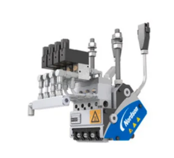
The Universal slice metering applicator is designed to apply thermoplastic hot melt adhesive to nonwoven products. Universal slice applicators are configurable, which means each applicator is constructed according to specific choices made during the ordering process. Reference drawings specific to your applicator are provided with this manual.
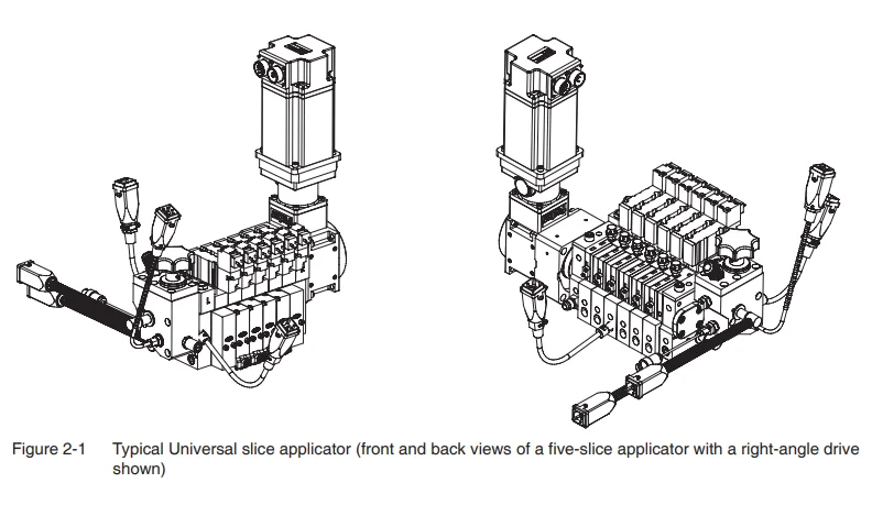
Key Parts
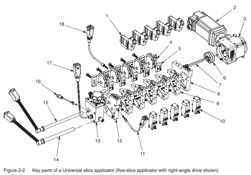
- Solenoid valve
- Motor
- Reducer
- Pump
- Adhesive diverter plate
- Pump packing
- Pump shaft
- End slice (right)
- Middle slice (one of five)
- Dispensing module
- Adhesive temperature sensor
- End slice (left)
- Filter block
- Air heater
- Adhesive heater
- Miniature pressure transducer (option)
- Immersion sensor (option)
- Air temperature sensor
Note: The front of the applicator is always the side on which the modules are installed.
Note: The optional pump temperature sensor is not shown.
Theory of Operation
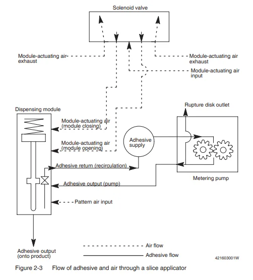
Operation of the Universal slice applicator begins with the introduction of three process variables: melted adhesive, module-actuating air, and heated pattern air. Figure 2-3 shows the flow of adhesive and air through the applicator.
Melted adhesive flows from the melter through a single supply hose to the adhesive inlet on the filter block. The adhesive then flows through the manifold slices to the dispensing modules. Solenoid valves supply actuating air to the modules, allowing adhesive to flow into the nozzles or dies installed on the modules. Heated pattern air may also be supplied to the applicator, causing the adhesive exiting the nozzles or dies to produce a spray pattern. When a module is closed, the adhesive is recirculated back through the pump.
Major Assemblies
The applicator consists of the following major assemblies:
- A customer-specified number of manifold “slices” onto which a metering pump, adhesive diverter plate, dispensing module, and solenoid valve may be mounted. The manifold slices are flanked by end slices.
- a filter block assembly,
- a motor, a reducer, and a shaft assembly to drive the metering pumps
Manifold Slices
The applicator manifold is composed of 25-mm (0.984 in.) left-end and right-end slices, along with however many 25-mm (0.984 in.) manifold slices are specified by the customer.
Mounted on each manifold slice are the following components that, depending on their configuration, affect the flow of adhesive and air through the slice:
- pump
- dispensing module
- solenoid valve and heat isolation gasket assembly or block-off plate
- adhesive diverter plate
Figures 2-4 and 2-5 show the components typically mounted on a manifold slice.
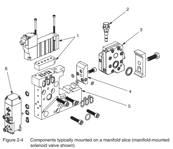
- Manifold-mounted solenoid valve and heat isolation gasket
- Rupture disk
- Pump
- Adhesive diverter plate
- Manifold slice
- Module
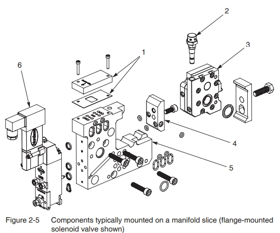
- Block-off plate and gasket
- Rupture disk
- Pump
- Adhesive diverter plate
- Manifold slice
- Module with flange-mounted solenoid valve
Pumps
Mounted on each manifold slice is a metering gear pump. Many standard pump sizes are available. Figure 2-6 shows the key components of a pump.
Through the use of an adhesive diverter plate, the pumps can be configured to feed adhesive to one module only (for true metering operation) or to multiple modules (for semi-metering, or pressure-fed, operation). For more information on the adhesive diverter plate, refer to Adhesive Diverter Plate later in this section.
Pumps can be easily replaced using a special tool known as a pump puller. Refer to Tools and Supplies in Section 8, Parts, for the part number.
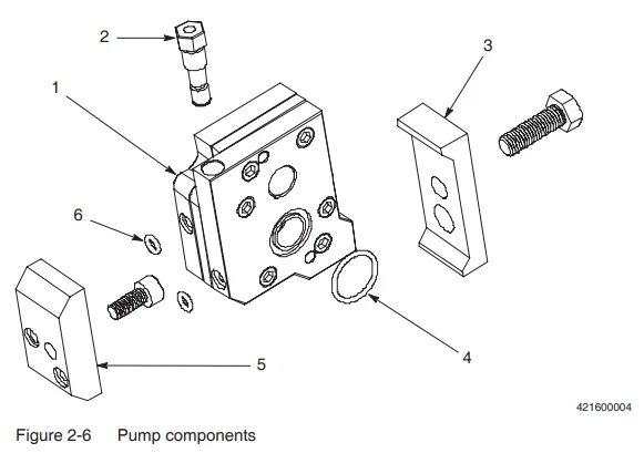
- Pump
- Rupture disk
- Pump clamp
- Pump O-ring
- Adhesive diverter plate
- Adhesive diverter plate O-ring
Rupture Disks
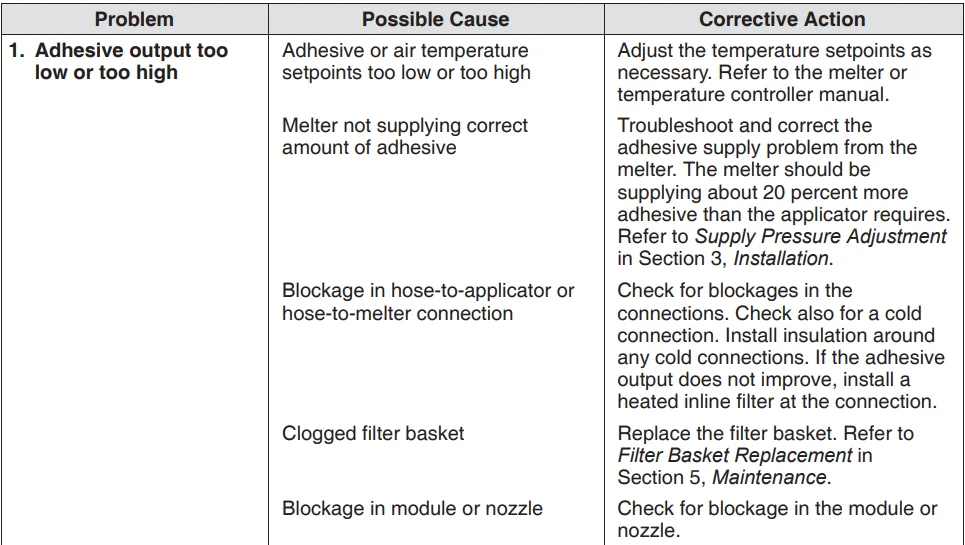
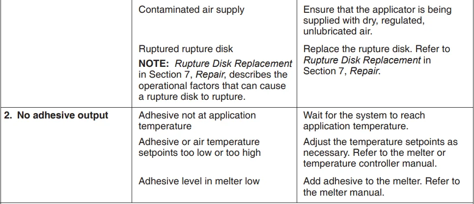
Rupture disks are safety devices installed in each slice applicator pump to prevent high-pressure situations. Figure 2-6 shows the location of a rupture disk. If any blockages occur downstream of the pump output to the module, the pressure in the system will build until the rupture disk bursts at approximately 114 bar (1,650 psi), plus or minus a 3 percent tolerance.
Operational factors that can cause the pressure in a slice applicator system to build to the point at which a rupture disk bursts include the following:
- nozzle clogging
- char or debris buildup in the applicator between the pump output and a module
- a recirculation port blocked with char or debris
- char or debris buildup inside a module
- startup of the pumps before the system has reached the application temperature (in which case the adhesive viscosity may be too high)
When a rupture disk bursts to prevent a high-pressure situation, a new rupture disk must be installed. Refer to Rupture Disk Replacement in Section 7, Repair.
Dispensing Modules
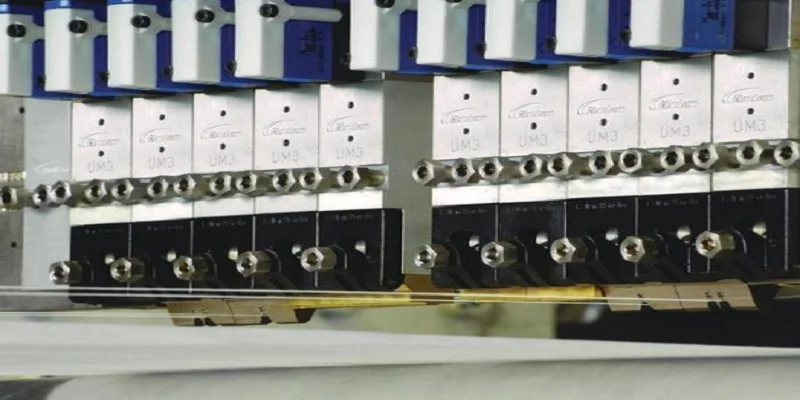
The three-way adhesive dispensing modules used on the applicator have quick reaction times and provide consistency across applications. The most commonly used modules are the UM3 modules shown in Figure 2-7. The UM3 coating module is used in bead and slot applications. The UM3 spray module, either directly or through the use of an adapter, can be configured for a variety of spray applications, such as Controlled Fiberization, Summit, and meltblown applications, as well as for bead applications.
A block-off module is also available, allowing you to block off the adhesive output from an individual slice. Refer to the module documentation for information on the modules that may be used with the applicator.
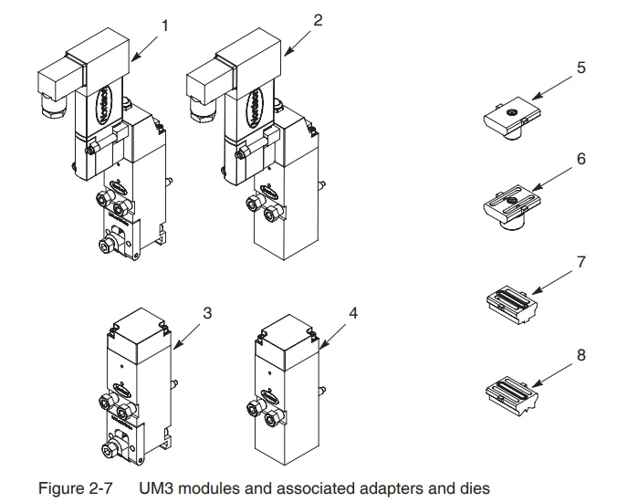
- UM3 spray module with flange-mounted solenoid valve
- UM3 coating module with flange-mounted solenoid valve
- UM3 spray module (for use with manifold-mounted solenoid valves)
- UM3 coating module (for use with manifold-mounted solenoid valves)
- Bead adapter
- Controlled Fiberization (CF) adapter
- Summit die (no adapter required)
- Meltblown die (no adapter required)
Solenoid Valves
Air is supplied to the applicator for two reasons:
- To open, or actuate, the modules (known as module-actuating air, or sometimes as control air)
- If applicable, to supply the modules with air that is combined with the adhesive exiting the modules to produce a variety of pattern types (known as pattern air, or sometimes as process air)
Solenoid valves are used to control the module-actuating air. Depending on the type of modules installed on the applicator, solenoid valves may be installed on the applicator manifold (manifold-mounted) or on the modules themselves (flange-mounted).
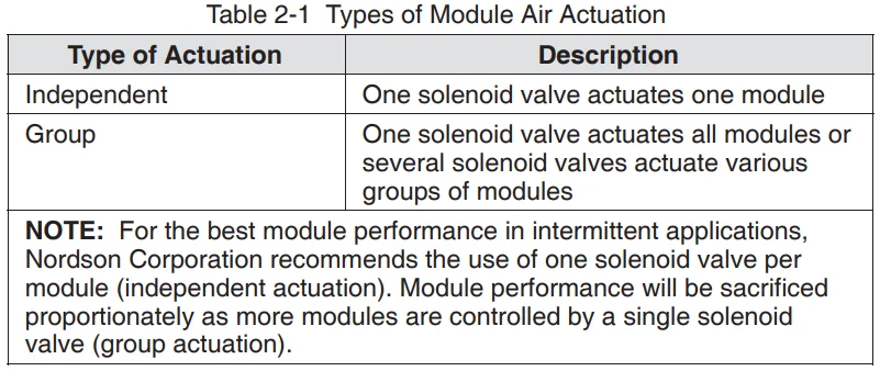
When manifold-mounted solenoid valves are present, heat isolation gaskets and block-off plates are used to control the air actuation for a single module, for all modules, or for various groupings of modules, as shown in Table 2-1.
Figure 2-8 shows an example of how solenoid valves, heat isolation gaskets, and block-off plates might be configured.
When flange-mounted solenoid valves are present, solenoid valve diverter plates or block-off plates are used. Figure 2-9 shows an example of how solenoid valves, solenoid valve diverter plates, and block-off plates might be configured.
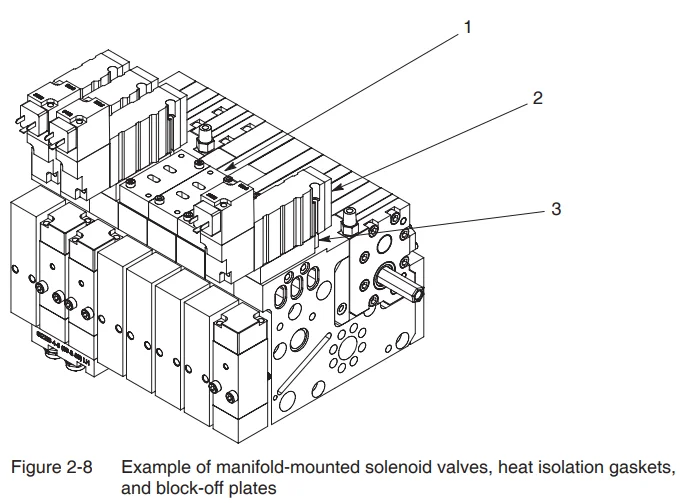
- Block-off plate
- Solenoid valve
- Heat isolation gasket
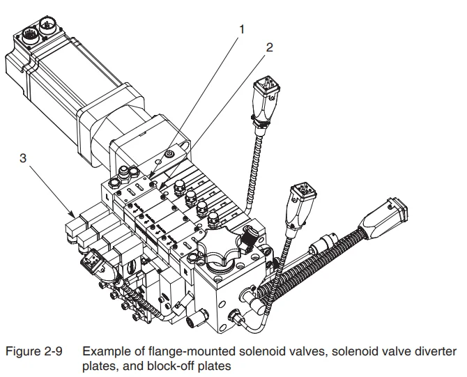
- Block-off plate
- Solenoid valve diverter plate
- Solenoid valve
Heat Isolation Gaskets
Heat isolation gaskets are installed between a manifold-mounted solenoid valve and a manifold slice to direct the air supply toward a single module, a single module and adjacent modules, or only adjacent modules, depending on which side of the gasket is positioned up or down, as shown in Figure 2-10.
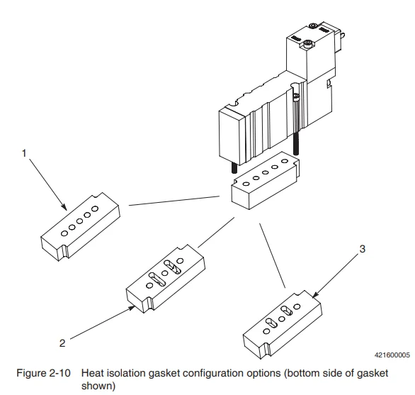
- Independent actuation
- Grouped actuation, left and right air flow.
- Grouped actuation, left or right air flow (depending on the orientation of the gasket)
Solenoid Valve Diverter Plates
Solenoid valve diverter plates are installed on manifold slices on which a UM3 module with a flange-mounted solenoid valve is used. The solenoid valve diverter plate blocks the air flow ports on the top of the manifold slice.
NOTE: Solenoid valve diverter plates are used only when UM3 flange-mount style modules are present.
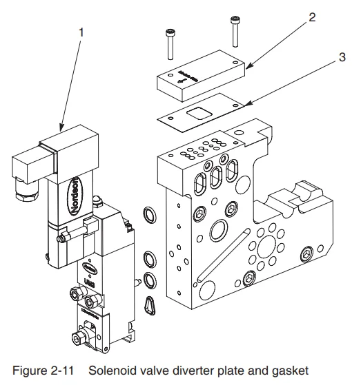
- UM3 module with flange-mounted solenoid valve
- Solenoid valve diverter plate
- Gasket
Block-Off Plates
Block-off plates are installed on slices that do not have a solenoid valve. A block-off plate can block the air flow completely or (like a heat isolation gasket) direct the air flow to a single module, a single module and adjacent modules, or only adjacent modules, depending on which side of the plate is positioned up or down, as shown in Figure 2-12.
NOTE: Block-off plates are used only when UM3 manifold-mount style modules are present.
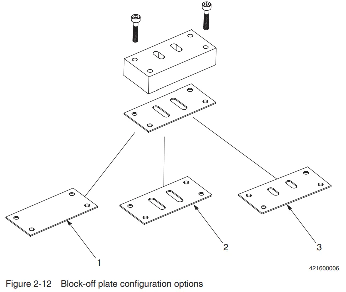
- Air flow blocked
- Left and right air flow
- Left or right air flow (depending on the orientation of the plate)
Adhesive Diverter Plate
An adhesive diverter plate is installed between a manifold slice and a pump to direct the flow of adhesive to the modules. Using an adhesive diverter plate, a pump can be configured to feed adhesive to one module only (for true metering operation) or to multiple modules (for semi-metering, or pressure-fed, operation). Flow rate accuracy decreases proportionately as the number of modules fed by one pump increases. Figure 2-13 shows the location of the adhesive diverter plate.
NOTE: Refer to Manifold (Middle) Slice Parts in Section 8, Parts, for a table that shows the configuration possibilities for the adhesive diverter plate.
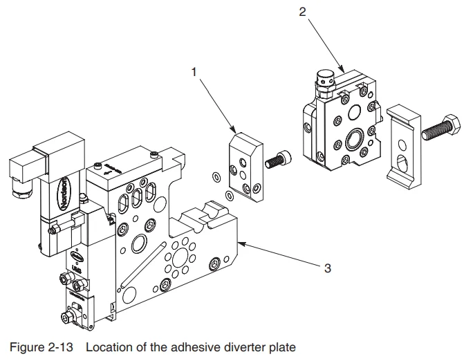
- Adhesive diverter plate
- Pump
- Manifold slice
Filter Block
The filter block, located at the end of the applicator opposite the motor, is the point at which adhesive enters the applicator. The filter block includes the hose fitting, the filter, the drain valve, and the pre- and post-pressure transducer plugs, into which optional pressure transducers may be installed. Figure 2-14 shows the key components of the filter block.
Preventive maintenance for the applicator includes changing the filter basket on an as-needed basis to ensure consistent operation of the applicator. Pressure readings supplied by pressure transducers (if present) can help determine when the filter basket needs to be changed.
The drain valve is used to relieve pressure in the system for safety during maintenance and repair activities.
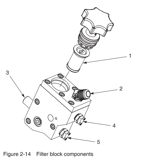
- Filter basket
- Hose fitting
- Drain valve
- Pre-filter pressure transducer plug
- Post-filter pressure transducer plug
Motor
The applicator pumps are driven by a motor, reducer, and shaft assembly, also known as the drive. The motor and reducer are available in many configurations, including inline and right-angle configurations, as shown in Figure 2-15. The reducer ratio is always 10:1. The shaft length varies depending on the number of slices in the applicator.
The drive may be mounted on either the left or right side of the applicator. Moving the drive from one side of the applicator to the other is known as changing the “hand” of the applicator. When this occurs, the rotational direction of the motor must be checked to ensure proper operation. The procedure for checking the motor rotational direction is provided in Section 7, Repair.
NOTE: The front of the applicator is always the side on which the modules are installed.
The motor speed is controlled through the melter control system or through a Universal slice controller, although other customer-specified control equipment may be used.
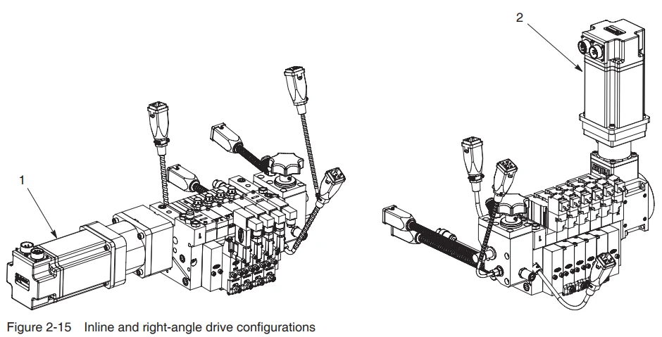
- Inline drive
- Right-angle drive
Heating and Temperature Control
Heating and temperature control of the Universal slice applicator are accomplished by the cartridge heaters and temperature sensors installed on the applicator.
Heaters
Heating of the adhesive and air (if used) that flows through the manifold slices is accomplished through cartridge-type heaters that slide through all of the slices present on the applicator. All heaters have a quick-change plug. The heater length varies depending on the number of slices present. Figure 2-16 shows the location of the adhesive and air heaters on an applicator.
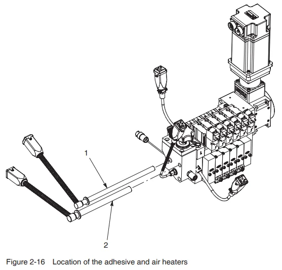
- Adhesive heater
- Air heater
Temperature Sensors
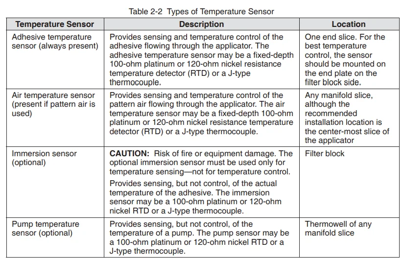
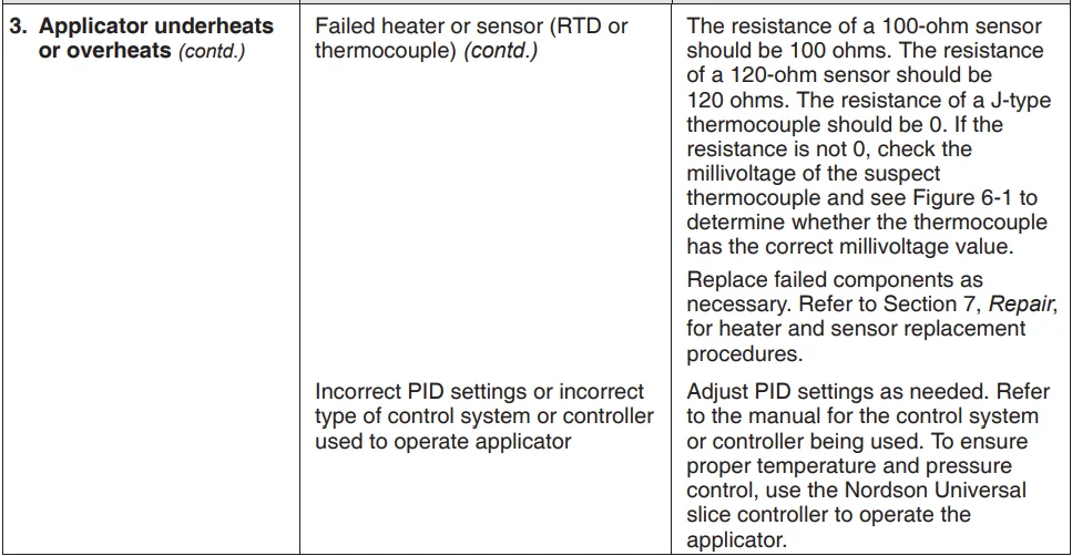
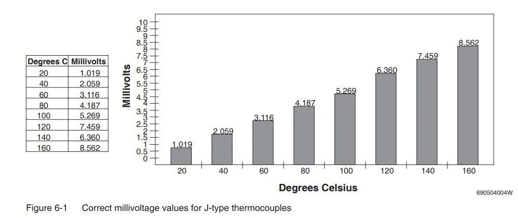
Temperature sensing and control are accomplished through 100-ohm platinum or 120-ohm nickel resistance temperature detectors (RTDs) or J-type thermocouples. Four types of temperature sensors may be present on the applicator—refer to Table 2-2. Figure 2-17 shows the location of the sensors on the applicator.
The applicator uses a modular quick-change plug system for all sensors. A quick-change, bayonet-style thermowell is used for the installation of the adhesive and air temperature sensors. All manifold slices can accommodate a temperature sensor for heated air. By moving the air temperature sensor from slice to slice, temperature profiles may be evaluated for each slice, enhancing diagnostic capabilities.
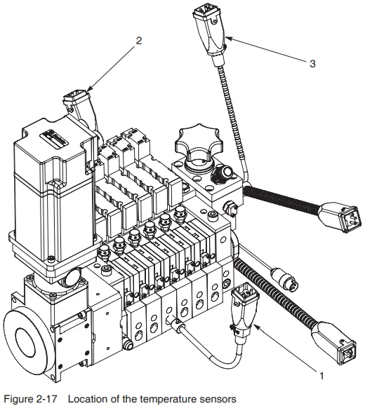
- Air temperature sensor
- Adhesive temperature sensor
- Immersion sensor (option)
Note: The optional pump temperature sensor is not shown.
Pressure Monitoring
Optional pressure transducers may be present on your applicator. Pressure transducers allow you to monitor the hydraulic pressure at the following points in the applicator:
- Pre-filter—A pre-filter pressure transducer monitors the pressure of the adhesive flow before it enters the applicator.
- Post-filter—A post-filter pressure transducer monitors the pressure of the adhesive flow after the filter but before the pumps. Comparing the differential between the pre-filter and post-filter pressure readings is the best way to determine when the filter basket needs to be replaced.
- Pump—A pump pressure transducer monitors the pressure of the adhesive flow between the pump output and the module (known as the application pressure). Tracking this pressure reading provides the best way to predict module failure or nozzle clogging.
Figure 2-18 shows the two types of pressure transducer: standard (1/2-20 threaded) and miniature. Standard pressure transducers can be installed only in the pre-filter and post-filter locations on the filter block. Miniature pressure transducers, however, can be installed in the filter block or in any pump.
Pressure transducers are connected to the customer’s pressure monitoring equipment (melter control system, Universal slice controller, etc.) via pressure transducer cables. Extension cables may be used if needed.
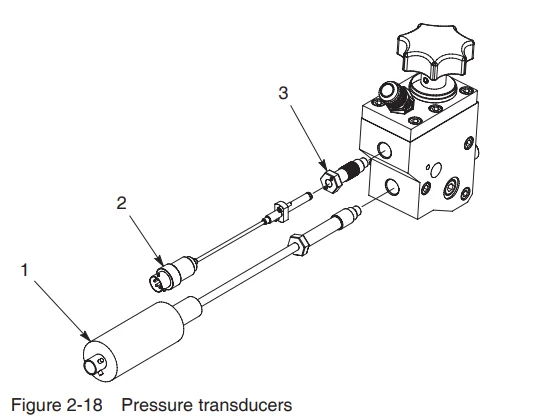
- Standard pressure transducer
- Miniature pressure transducer
- Adapter fitting (required only for miniature transducers)
Operation
![]() WARNING: Allow only personnel with appropriate training and experience to operate or service the equipment. The use of untrained or inexperienced personnel to operate or service the equipment can result in injury, including death, to themselves and others, and damage to the equipment.
WARNING: Allow only personnel with appropriate training and experience to operate or service the equipment. The use of untrained or inexperienced personnel to operate or service the equipment can result in injury, including death, to themselves and others, and damage to the equipment.
Introduction
This section provides procedures for operating the applicator. Before you operate the applicator for the first time, make sure you have
- completed the installation procedures in Section 3, Installation
- completed the initial startup, applicator flushing, and supply pressure adjustment procedures in Section 3, Installation
Startup
Procedures for starting and stopping the applicator vary depending on the type of melter you are using. Refer to the melter manual for complete startup and shutdown procedures.
- Heat the system to application temperature.
- Turn on the module-actuating air.
- Turn on the pattern air.
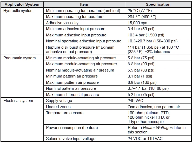
NOTE: Recommended settings for the module-actuating air pressure, pattern air pressure, and system hydraulic pressure are provided in Applicator Specifications in Section 9, Technical Data. - Start the melter pump(s). The melter pump(s) should supply about 20 percent more adhesive than the applicator needs. Refer to Supply Pressure Adjustment in Section 3, Installation, as needed.
- Start the applicator pump. Refer to Applicator Specifications in Section 9, Technical Data, for the minimum, maximum, and recommended pump speeds.
- Start the production line.
- During operation, monitor temperatures and pressures. Both should remain constant.
Shutdown
Procedures for starting and stopping the applicator vary depending on the type of melter you are using. Refer to the melter manual for complete startup and shutdown procedures.
- Stop the production line.
- Stop the applicator pump.
- Stop the melter pump(s).
- Relieve system pressure as follows:
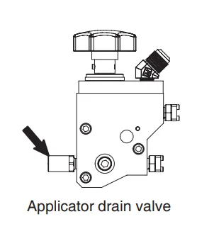
- Place a drain pan under the applicator drain valve.
- Turn the drain valve screw one turn counterclockwise and allow the adhesive to drain from the drain valve.
- Tighten the drain valve screw to close the drain valve
- Remove power to the applicator.
- Turn off the module-actuating air.
- Turn off the pattern air.
Maintenance
![]() WARNING: Allow only personnel with appropriate training and experience to operate or service the equipment. The use of untrained or inexperienced personnel to operate or service the equipment can result in injury, including death, to themselves and others, and damage to the equipment.
WARNING: Allow only personnel with appropriate training and experience to operate or service the equipment. The use of untrained or inexperienced personnel to operate or service the equipment can result in injury, including death, to themselves and others, and damage to the equipment.
Introduction
This section contains a recommended maintenance schedule and procedures for properly maintaining your applicator. Attempting any other maintenance procedures can result in equipment damage, improper system operation, or personal injury.
Maintenance Schedule
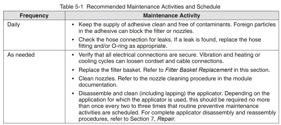
Table 5-1 provides recommended maintenance activities and a schedule for performing those activities. Base how often you perform maintenance on your operating conditions.
Filter Basket Replacement
The filter assembly contains a disposable basket-style filter that captures debris in the adhesive before it enters the manifold. This filter basket must be periodically replaced to prevent restriction of the adhesive flow.

NOTE: Cleaning and reuse of the filter basket is not recommended.
CAUTION: Risk of filter damage. Do not attempt to remove or disassemble the filter assembly until the adhesive in the system has reached the softening point.
- Heat the system to application temperature.
- Stop the supply of adhesive to the applicator.
- Relieve pressure from the applicator by turning the drain valve screw (located on the front of the filter block) one turn counterclockwise.
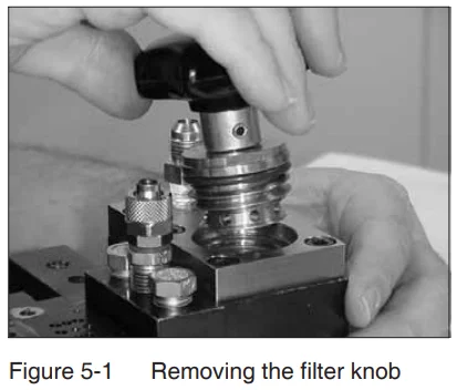
- See Figure 5-1. Unscrew the filter knob and remove the knob assembly.

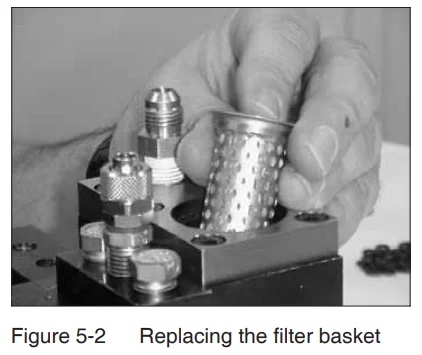
- See Figure 5-2. Remove the filter basket and discard it.
- Install a new filter basket and ensure that it is seated properly in the cavity.

- Reinstall the filter knob.
- Restore the system to normal operation.
Troubleshooting
![]() WARNING: Allow only personnel with appropriate training and experience to operate or service the equipment. The use of untrained or inexperienced personnel to operate or service the equipment can result in injury, including death, to themselves and others, and damage to the equipment.
WARNING: Allow only personnel with appropriate training and experience to operate or service the equipment. The use of untrained or inexperienced personnel to operate or service the equipment can result in injury, including death, to themselves and others, and damage to the equipment.
Introduction
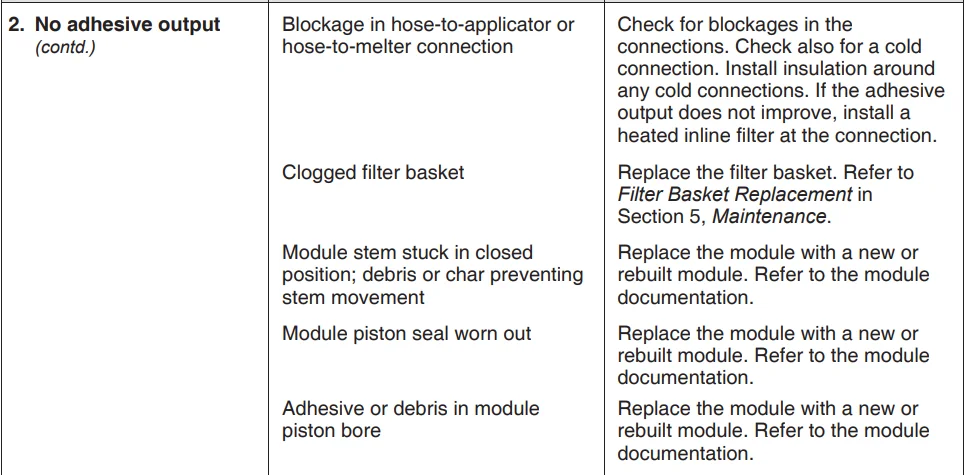
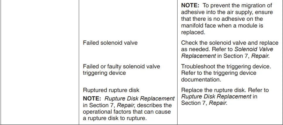
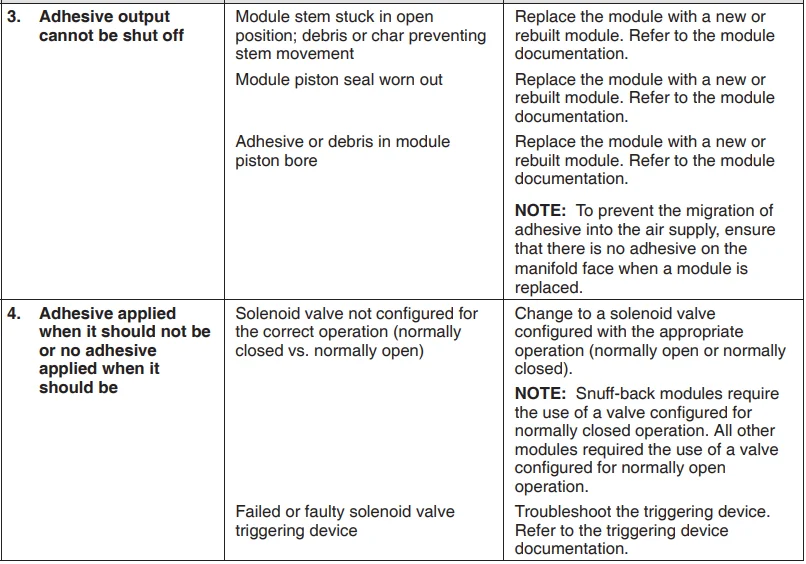
Troubleshooting begins when the flow of adhesive from the applicator stops or diminishes unexpectedly, or when a control system alerts you of a problem through an alarm or visual display. This section covers only the most common problems you may encounter. If you cannot solve a problem with the information given here, contact your local Nordson representative for help.
For additional troubleshooting information, refer to the manuals provided with the other equipment used in the hot melt system.
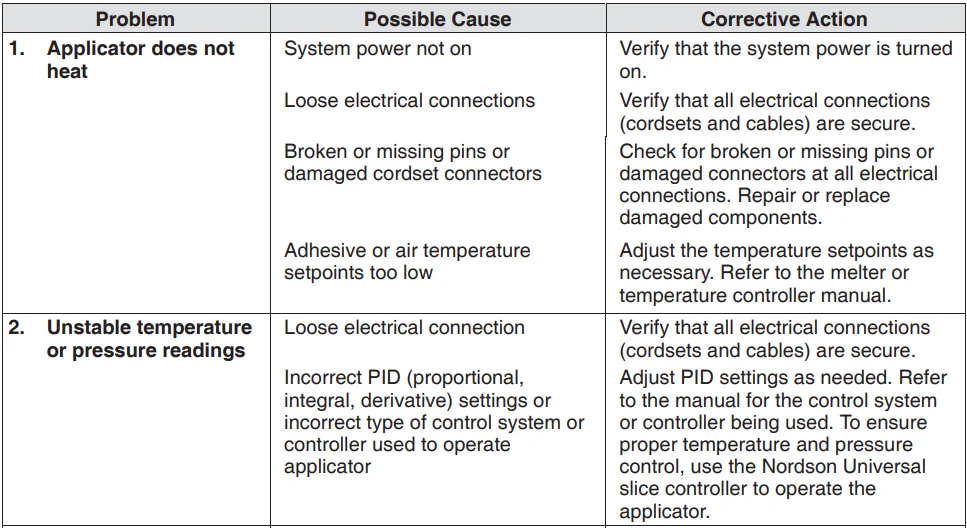
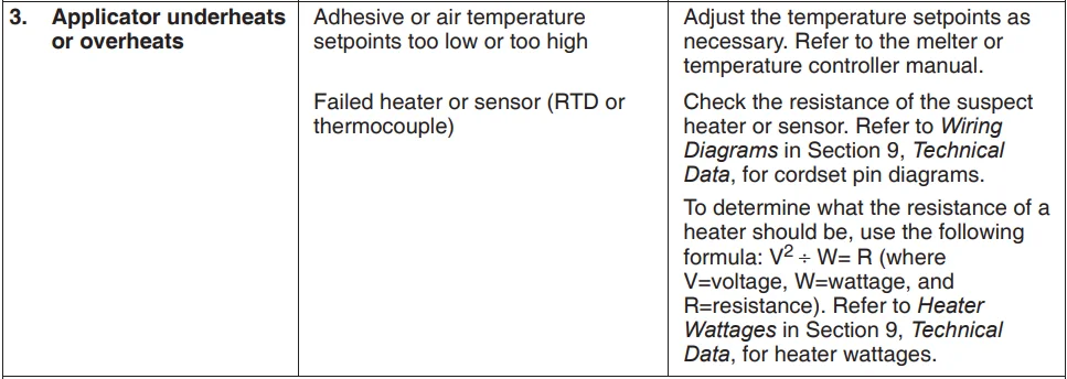
Applicator Heating Problems
![]() WARNING: Risk of personal injury or death. Allow only qualified personnel to perform electrical installation, troubleshooting, or repair procedures. Before performing any electrical procedure, review Section 1, Safety, and disconnect and lock out electrical power to the system.
WARNING: Risk of personal injury or death. Allow only qualified personnel to perform electrical installation, troubleshooting, or repair procedures. Before performing any electrical procedure, review Section 1, Safety, and disconnect and lock out electrical power to the system.
Adhesive Output Problems
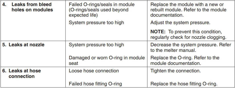
Adhesive Leakage Problems
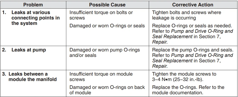
CAUTION: Operation of the applicator motor in the wrong direction for extended periods of time will severely damage the applicator, causing general O-ring and seal failure and leakage at various points throughout the applicator. To ensure that the motor is operating in the correct direction, refer to Motor Rotational Check in Section 7, Repair.
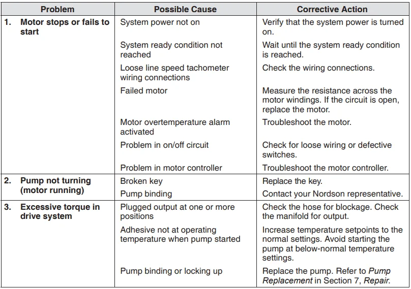
Pump and Drive Problems
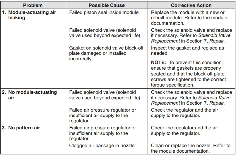
Air Supply Problems
Pattern Control Problems
Refer to the module documentation.
Technical Data
Applicator Specifications
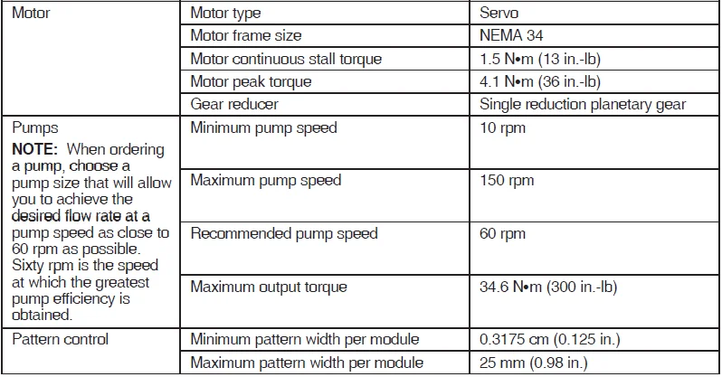
Fluid Compatibility
Rated for use with all commercially available, pressure-sensitive, hot melt adhesives, except any compounds that contain polyamides.
Disclaimer
The equipment specifications above will be under warranty according to Nordson’s standard agreements. Nordson will cover the cost of repair and or replacement of the equipment due to failure. However, due to situations beyond our control, such as misuse, equipment modification, unreasonable use, neglect, and lack of maintenance, Nordson will not be liable for personal injuries and associated costs thereof due to equipment failure under such conditions.
Nomenclature
Cv—pneumatic conductance is reported as a number expressing the ability of a fluid to flow under a Δp (pressure drop) and is often referred to as flow capability, or more commonly known as flow coefficient.
Applicator Dimensions
Refer to the applicator-specific drawing provided with this manual for the dimensions of your applicator.
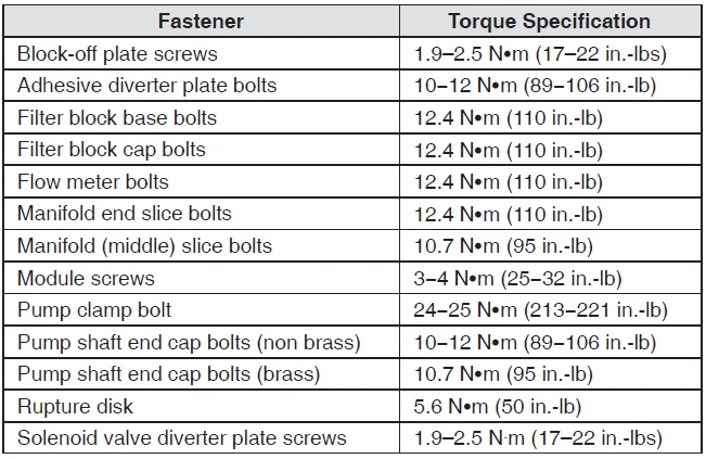
Torque Specifications
These torque specifications are also stated within the appropriate repair procedures.
Wiring Diagrams
Electrical Schematic
Refer to the reference drawings provided with the applicator.
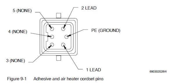
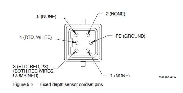
Cordset Pin Positions
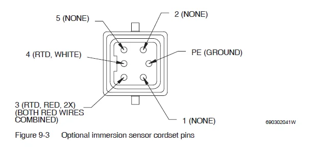
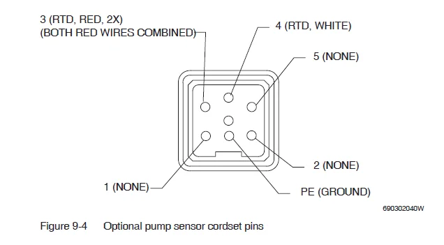
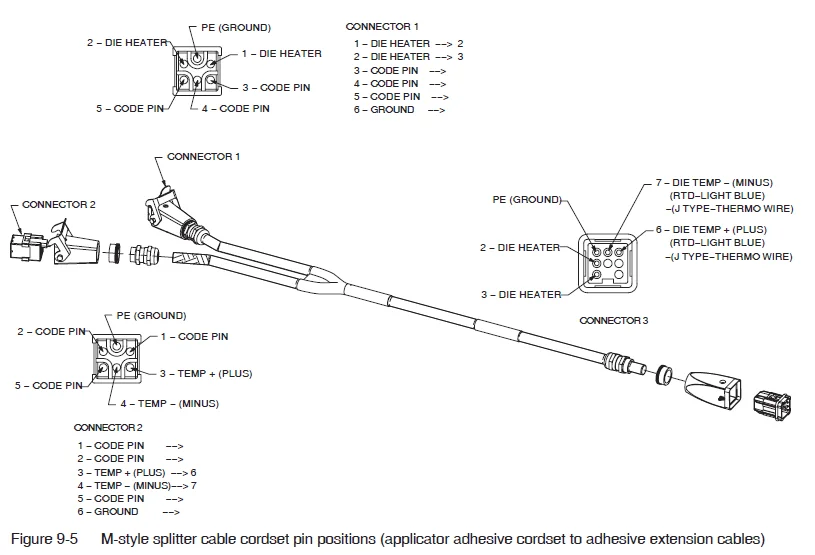
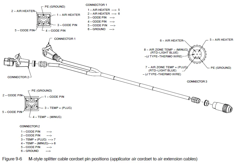
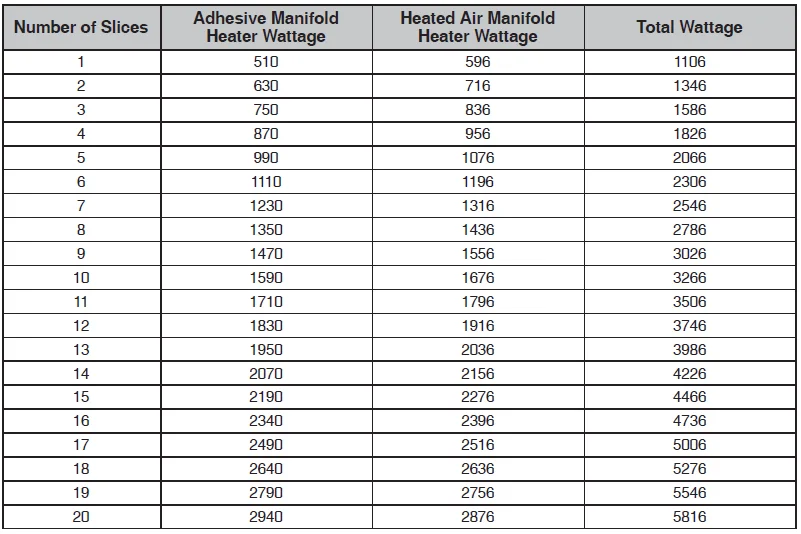
Heater Wattages
For more manuals by Nordson, visit ManualsLibraryy
Nordson Universal Slice Applicator- FAQs
What is the Nordson Universal Slice Applicator used for?
It is designed for precise hot melt adhesive application in packaging, converting, and product assembly operations.
How does the applicator control adhesive flow?
The unit uses an adjustable slot nozzle that delivers a uniform, thin adhesive layer for accurate and repeatable results.
Can the slice applicator handle different adhesive types?
Yes, it is compatible with most standard hot melt adhesives, ensuring flexibility across multiple production needs.
How do I adjust the coating width?
The applicator allows quick nozzle and shim adjustments so operators can set the exact width required for the job.
What temperature should the applicator operate at?
It must be heated to the adhesive manufacturer’s recommended temperature range, typically between 150°C and 200°C.
How do I clean the applicator safely?
Turn off and cool the system before cleaning. Use only approved Nordson cleaning tools and avoid sharp objects to prevent nozzle damage.
How often should maintenance be performed?
Routine checks of filters, nozzles, and seals are recommended. Regular preventive maintenance improves performance and extends equipment life.
Can the applicator be integrated with existing Nordson systems?
Yes, the Universal Slice Applicator is designed for easy integration with Nordson melters and control systems.

