Pioneer VSX 1020 Audio Video Multi Channel Receiver
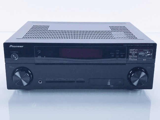
Before you start
Checking what’s in the box
Please check that you’ve received the following supplied accessories:
- Set up the microphone (cable: 5 m (16.4 ft.))
- Remote control unit
- AAA size IEC R03 dry cell batteries (to confirm system operation) x2
- AM loop antenna
- FM wire antenna
- iPod cable
- These operating instructions
Installing the receiver
- When installing this unit, make sure to put it on a level and stable surface.
Don’t install it on the following places:- on a color TV (the screen may distort)
- near a cassette deck (or close to a device that gives off a magnetic field). This may interfere with the sound.
- In direct sunlight
- In damp areas
- In extremely hot or cold areas
- In places where there is vibration or other movement
- In very dusty places
- In places that have hot fumes or oils (such as a kitchen)
- Do not touch this receiver’s bottom panel while the power is on or just after it is turned off. The bottom panel becomes hot when the power is on (or right after it is turned off) and could cause burns.
Loading the batteries

The batteries included with the unit are for checking initial operations; they may not last over a long period. We recommend using alkaline batteries that have a longer life.
CAUTION
Incorrect use of batteries may result in such hazards as leakage and bursting. Observe the following precautions:
- Never use new and old batteries together.
- Insert the plus and minus sides of the batteries properly according to the marks in the battery case.
- Batteries with the same shape may have different voltages. Do not use different batteries together.
- When disposing of used batteries, please comply with governmental regulations or environmental public instructions that apply in your country or area.
WARNING
Do not use or store batteries in direct sunlight or other excessively hot places, such as inside a car or near a heater. This can cause batteries to leak, overheat, explode, or catch fire. It can also reduce the life or performance of batteries.
Controls and displays
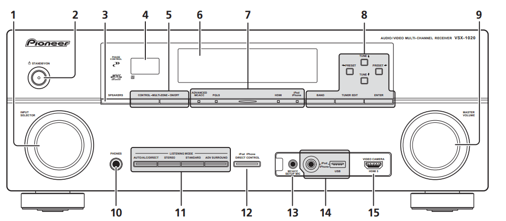
- INPUT SELECTOR dial
Select an input function.  STANDBY/ON
Switches the receiver between on and standby.- SPEAKERS
See Switching the speaker terminal on page 72. - Remote sensor
Receives the signals from the remote control (see Operating range of remote control unit on page 13). - MULTI-ZONE controls
If you’ve made MULTI-ZONE connections (see MULTI-ZONE setup on page 30) use these controls to control the sub-zone from the main zone (see Using the MULTI-ZONE controls on page 72). - Character display
See Display on page 10. - Indicators
- ADVANCED MCACC – Lights when EQ is set to ON in the AUDIO PARAMETER menu.
- PQLS – Lights when the PQLS feature is active (page 65).
- HDMI – Blinks when connecting an HDMI-equipped component; lights when the component is connected (page 23). iPod/iPhone – Lights to indicate iPod/iPhone is connected (page 43).
- Tuner controls
- BAND – Switches between AM and FM radio bands (page 48).
- TUNER EDIT – Use with TUNE ⇑/⇓,
- PRESET ⇐/⇒ and ENTER to memorize and name stations for recall (page 48).
- TUNE ⇑/⇓ – Find radio frequencies (page 48).
- PRESET⇐/⇒– Find preset stations (page 48).
- MASTER VOLUME dial
- PHONES jack
Connect the headphones. When the headphones are connected, there is no sound output from the speakers. - Listening mode buttons
- AUTO/ALC/DIRECT – Switches between Auto Surround (page 56), Auto Level Control mode and Stream Direct mode (page 59).
- STEREO – Switches between stereo playback and Front Stage Surround Advance modes (page 59).
- STANDARD – Press for Standard decoding and to switch between the various 2 Pro Logic IIx and Neo:6 options (page 56).
- ADV SURROUND – Switch between the various surround modes (page 58).
- iPod iPhone DIRECT CONTROL
Change the receiver’s input to the iPod and enable iPod operations on the iPod (page 44). - MCACC SETUP MIC jack
Connect the supplied microphone (page 37). - iPod/iPhone/USB terminals
Connect your Apple iPod as an audio and video source, or connect a USB device for audio and photo playback (page 33). - HDMI input connector
Use for connection to a compatible HDMI device (Video camera, etc.)(page 32).
Display

- SIGNAL indicators
Light to indicate the currently selected input signal. AUTO lights when the receiver is set to select the input signal automatically (page 60). - Program format indicators
Light to indicate the channels being digital input.- L/R – Left front/Right front channel
- C – Center channel
- SL/SR – Left surround/Right surround channel
- LFE – Low frequency effects channel (the (( )) indicators light when an LFE signal is being input)
- XL/XR – Two channels other than the ones above
- XC – Either one channel other than the ones above, the mono surround channel or matrix encode flag
- Digital format indicators
Light is emitted when a signal encoded in the corresponding format is detected. DIGITAL – Lights with Dolby Digital decoding.
 DIGITAL PLUS – Lights with Dolby Digital Plus decoding.
 TrueHD – Lights with Dolby TrueHD decoding.
- DTS – Lights with DTS decoding.
- DTS HD – Lights with DTS-HD decoding.
- 96/24 – Lights with DTS 96/24 decoding.
- WMA9 Pro – Lights to indicate that a WMA9 Pro signal is being decoded.
- DSD PCM – Light during DSD (Direct Stream Digital) to PCM conversion with SACDs.
- PCM – Lights during playback of PCM signals.
- MSTR – Lights during playback of DTS-HD Master Audio signal.
- MULTI-ZONE
Lights when the MULTI-ZONE feature is active (page 72). - SOUND
Lights when any of the Midnight, Loudness or tone controls feature is selected (page 67). Lights when Dialog Enhancement is switched on. - PQLS
Lights when the PQLS feature is active (page 65). - S.RTRV
Lights when the Sound Retriever function is active (page 68). - Listening mode indicators
- AUTO SURROUND – Lights when the Auto Surround feature is switched on (page 56).
- ALC – Lights when the ALC (Auto level control) mode is selected (page 59).
- STREAM DIRECT – Lights when Direct/Pure Direct is selected (page 59).
- ADV.SURROUND – Lights when one of the Advanced Surround modes has been selected (page 58).
- STEREO – Lights when stereo listening is switched on (page 58).
- STANDARD – Lights when one of the Standard Surround modes is switched on
(page 56).
 (PHASE CONTROL)
Lights when the Phase Control is switched on(page 61).- Analog signal indicators
Light to indicate reducing the level of an analog signal (page 74). - Tuner indicators
- TUNED – Lights when a broadcast is being received.
- STEREO – Lights when a stereo FM broadcast is being received in auto stereo mode.
- MONO – Lights when the mono mode is set using MPX.

Lights when the sound is muted (page 13).- Master volume level
Shows the overall volume level. “—” indicates the minimum level, and “+12dB” indicates the maximum level. - Input function indicators
Light to indicate the input function you have selected. - Scroll indicators
Light when there are more selectable items when making the various settings. - Speaker indicators
Indicates the speaker terminal, A and/or B, to which the audio signal output is currently set
(page 72). - SLEEP
Lights when the receiver is in sleep mode (page 74). - Matrix decoding format indicators
 PRO LOGIC IIx – This light indicates
 Pro Logic II /
 Pro Logic IIx decoding (page 56).
- Neo:6 – When one of the Neo:6 modes of the receiver is on, this light indicates
Neo:6 processing (page 56).
- Character display
Displays various system information. - Remote control mode indicator
Lights to indicate the receiver’s remote control mode setting. (Not displayed when set to 1.) (page 76)
Remote control
This section explains how to operate the remote control for the receiver.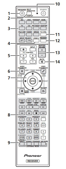
The remote has been conveniently color-coded according to component control using the following system:
- White – Receiver control, TV Control
- Blue – Other controls (See page 43, 45, 48, 50, 52, 53, and 82.)
 RECEIVER
This switches between standby and on for this receiver.- MULTI OPERATION – Use to perform multiple operations (page 80).
R.SETUP – Used to input the preset code when making remote control settings and to set the remote control mode (page 76). - Input function buttons
Press to select control of other components (page 76). - ZONE 2
Switch to perform operations in the subzone (page 73). - TV CONTROL buttons
These buttons are dedicated to controlling the TV assigned to TV CTRL button. – Turn on/off the power of the TV.
- INPUT – Select the TV input signal.
- CH +/– – Select channels.
- VOL +/– Adjust the volume on your TV.
- Receiver controls
Press RECEIVER first to access:- AUDIO PARAMETER – Use to access the Audio options (page 67).
- VIDEO PARAMETER – Use to access the Video options (page 70).
- HOME MENU – Use to access the Home Menu (pages 37, 40, 63, 85, 99 and 105).
- RETURN – Press to confirm and exit the current menu screen.
- ⇑/⇓/⇐/⇒, ENTER
Use the arrow buttons when setting up your surround sound system (page 85) and the Audio or Video options (page 67 or 70). - Receiver controls
Press RECEIVER first to access:- PHASE CTRL – Switch on/off Phase Control (page 61).
- STATUS – Check selected receiver settings (page 74).
- PQLS – Select PQLS setting (page 65).
- S. RETRIEVER – Press to restore CD-quality sound to compressed audio sources (page 68).
- MIDNIGHT – Switches to Midnight or Loudness listening (page 67).
- SIGNAL SEL – Select an input signal (page 60).
- MCACC – Switch between MCACC presets (page 60).
- SLEEP – Use to put the receiver in sleep mode and select the amount of time before sleep (page 74).
- CH LEVEL – Press repeatedly to select a channel, then use ⇐/⇒ to adjust the level
(page 102). - A.ATT – Attenuates (lowers) the level of an analog input signal to prevent distortion (page 74).
- DIMMER – Dims or brightens the display (page 74).
- LISTENING MODE controls
- AUTO/ALC/DIRECT – Switches between Auto Surround (page 56), Auto Level Control mode and Stream Direct mode (page 59).
- STEREO – Switches between stereo playback and Front Stage Surround Advance modes (page 59).
- STANDARD – Press for Standard decoding and to switch between the various
 Pro Logic IIx and Neo:6 options (page 56).
 - ADV SURR – Switch between the various surround modes (page 58).
- Remote control LED
Lights when a command is sent from the remote control (page 76). - TV CTRL
Set preset code of your TV’s manufacturer when controlling TV (page 77). - RECIVER
Switches the remote to control the receiver (used to select the white commands above the number buttons (SIGNAL SEL, etc.)). Switch to perform operations in the main zone. Also use to set up surround sound. - MASTER VOLUME +/–
Set the listening volume. - MUTE
Mutes the sound or restores the sound if it has been muted (adjusting the volume also restores the sound).
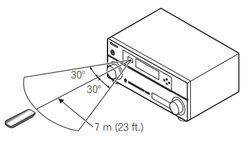
Operating range of the remote control unit
The remote control may not work properly if:
- There are obstacles between the remote control and the receiver’s remote sensor.
- Direct sunlight or fluorescent light is shining onto the remote sensor.
- The receiver is located near a device that is emitting infrared rays.
- The receiver is operated simultaneously with another infrared remote control unit.
Basic Setup
Changing the OSD display language (OSD Language)
The language used on the Graphical User Interface (GUI) screen can be changed.
- The explanations in these operating instructions are for when English is selected for the GUI screen.
- Switch on the receiver and your TV.
- Press RECEIVER on the remote control, then press HOME MENU.
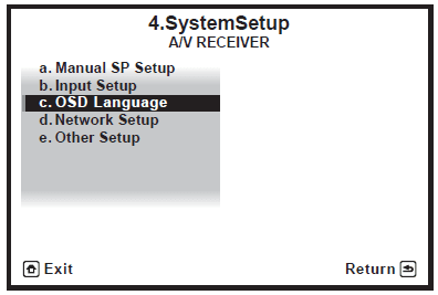
A GUI screen appears on your TV. Use ⇑/⇓/⇐/⇒ and ENTER to navigate through the screens and select menu items. Press RETURN to exit the current menu. - Select ‘System Setup’ from the HOME MENU.
- Select ‘OSD Language’ from the System Setup menu.

- Select the desired language.
- English
- French
- German
- Italian
- Spanish
- Dutch
- Russian
- Select ‘OK’ to change the language.
The setting is completed, and the System Setup menu reappears automatically.
Automatically setting up for surround sound (Auto MCACC)
The Auto MCACC Setup measures the acoustic characteristics of your listening area, taking into account ambient noise, speaker connection, and speaker size, and tests for both channel delay and channel level. After you have set up the microphone provided with your system, the receiver uses the information from a series of test tones to optimize the speaker settings and equalization for your particular room. Make sure you do this before moving on to playing a source on page 42.
Important
- Make sure the microphone and speakers are not moved during the Auto MCACC Setup.
- Using the Auto MCACC Setup will overwrite any existing settings for the MCACC preset you select.
- Before using the Auto MCACC Setup, the headphones should be disconnected.
CAUTION
- The test tones used in the Auto MCACC Setup are output at high volume.
- Switch on the receiver and your TV.
- Connect the microphone to the MCACC
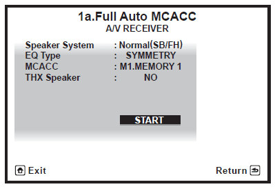
Set up the MIC jack on the front panel. Make sure there are no obstacles between the speakers and the microphone. If you have a tripod, use it to place the microphone so that it’s about ear level at your normal listening position. If you do not have a tripod, use some other object to install the microphone.1 The Full Auto MCACC display appears once the microphone is connected.2
- Select the parameters you want to set.3 If the speakers are connected using any setup other than the Front height setup, be sure to set the Speaker System before the Auto MCACC Setup. See the Speaker system setting on page 100.
- Speaker System 4 – Shows the current settings. Settings can be changed using the Speaker System in the Manual SP setup menu.
- EQ Type – This determines how the frequency balance is adjusted.
- MCACC – The six MCACC presets are used for storing surround sound settings for different listening positions. Simply choose an unused preset for now (you can rename it later in Data Management on page 97).
- THX Speaker – Select YES if you are using THX speakers (set all speakers to SMALL), otherwise leave it set to NO.
- Press RECEVIER and then select START.
- Follow the instructions on-screen.
Make sure the microphone is connected, and if you’re using a subwoofer, make sure it is switched on and set to a comfortable volume level. - Wait for the test tones to finish, then confirm the speaker configuration in the GUI screen.
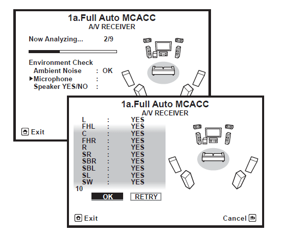
A progress report is displayed on-screen while the receiver outputs test tones to determine the
speakers present in your setup. Try to be as quiet as possible while it’s doing this.1 If no operations are performed for 10 seconds while the speaker configuration check screen is being displayed, the Auto MCACC Setup will resume automatically. In this case, you don’t need to select ‘OK’ and press ENTER in step 7.- With error messages (such as Too much ambient noise! or Check microphone.) select RETRY after checking for ambient noise (see Problems when using the Auto MCACC Setup on page 40) and verifying the mic connection. If there doesn’t seem to be a problem, you can simply select GO NEXT and continue.
 The configuration shown on-screen should reflect the actual speakers you have.
- If you see an ERR message (or the speaker configuration displayed isn’t correct), there
may be a problem with the speaker connection. If selecting RETRY doesn’t work, turn off the power and check the speaker connections. If there doesn’t seem to be a problem, you can simply use ⇑/⇓ to select the speaker and ⇐/⇒ to change the setting and continue. - If Reverse Phase is displayed, the speaker’s wiring (+ and –) may be inverted. Check the speaker connections.2
- If the connections were wrong, turn off the power, disconnect the power cord, and then reconnect properly. After this, perform the Full Auto MCACC procedure again.
- If the connections were right, select GO NEXT and continue.
- If you see an ERR message (or the speaker configuration displayed isn’t correct), there
- With error messages (such as Too much ambient noise! or Check microphone.) select RETRY after checking for ambient noise (see Problems when using the Auto MCACC Setup on page 40) and verifying the mic connection. If there doesn’t seem to be a problem, you can simply select GO NEXT and continue.
- Make sure ‘OK’ is selected, then press ENTER.
A progress report is displayed on-screen while the receiver outputs more test tones to determine the optimum receiver settings for Channel Level, Speaker Distance, Standing Wave, and Acoustic Cal EQ. Again, try to be as quiet as possible while this is happening. It may take 3 to 10 minutes. - The Auto MCACC Setup procedure is completed, and the Home Menu reappears automatically.3
Be sure to disconnect the microphone from this receiver upon completion of the Auto MCACC Setup. The settings made in the Auto MCACC Setup should give you excellent surround sound from your system, but it is also possible to adjust these settings manually using the Advanced MCACC menu on page 85 or the system and the other setup on page 99.1
Problems when using the Auto MCACC Setup
If the room environment is not optimal for the Auto MCACC Setup (too much background noise, echo off the walls, obstacles blocking the speakers from the microphone), the final settings may be incorrect. Check for household appliances (air conditioner, fridge, fan, etc.), that may be affecting the environment and switch them off if necessary. If there are any instructions showing in the front panel display, please follow them.
- Some older TVs may interfere with the operation of the microphone. If this seems to be happening, switch off the TV when doing the Auto MCACC Setup.
The Input Setup menu
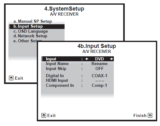
You only need to make settings in the Input Setup menu if you didn’t hook up your digital equipment according to the default settings (see Input function default and possible settings on page 41). In this case, you need to tell the receiver what equipment is hooked up to which terminal so the buttons on the remote control correspond to the components you’ve connected.
- Switch on the receiver and your TV. Use
 RECEIVER to switch on.
 - Press RECEVIER on the remote control, then press HOME MENU.
A Graphical User Interface (GUI) screen appears on your TV. Use ⇑/⇓/⇐/⇒ and ENTER to navigate through the screens and select menu items. Press RETURN to confirm and exit the current menu. - Select ‘System Setup’ from the HOME MENU.
- Select ‘Input Setup’ from the System Setup menu.

- Select the input function that you want to set up.
The default names correspond with the names next to the terminals on the rear panel (such as DVD or VIDEO), which, in turn, correspond with the names on the remote control. - Select the input(s) to which you’ve connected your component.
For example, if your DVD player only has an optical output, you will need to change the DVD input function’s Digital In setting from COAX-1 (default) to the optical input you’ve connected it to. The numbering (OPT-1 to 2) corresponds with the numbers beside the inputs on the back of the receiver.- If your component is connected via a component video cable to an input terminal other than the default, you must tell the receiver which input terminal your component is connected to, or else you may see the composite video signals instead of the component video signals.1
- When you’re finished, proceed to the settings for other inputs.
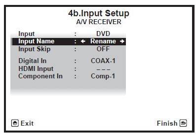
There are optional settings in addition to the assignment of the input jacks:- Input Name – You can choose to rename the input function for easier identification. Select Rename to do so, or Default to return to the system default.
- Input Skip – When set to ON, that input is skipped when selecting the input using INPUT SELECT or the front panel INPUT SELECTOR dial. (DVD and other inputs can be still be selected directly with the input function buttons.)

- When you’re finished, press RETURN.
You will return to the System Setup menu.
Input function default and possible settings
The terminals on the receiver generally correspond to the name of one of the input functions. If you have connected components to this receiver differently from (or in addition to) the defaults below, see the Input Setup menu on page 40 to tell the receiver how you’ve connected up. The dots![]() indicate possible assignments.
indicate possible assignments.
| Input function | Input Terminals | ||
| Digital | HDMI | Component | |
| DVD | COAX-1 | IN 1 | |
| BD | (BD) | ||
| TV/SAT | OPT-1 | ||
| DVR/BDR | OPT-2 | IN 2 | |
| VIDEO | |||
| HDMI 1 | (HDMI-1) | ||
| HDMI 2 | (HDMI-2) | ||
| HDMI 3 | (HDMI-3) | ||
| HDMI 4 | (HDMI-4) | ||
| HDMI 5 (front panel) | (HDMI-5) | ||
| INTERNET RADIO | |||
| iPod/USB | |||
| CD | COAX-2 | ||
| CD-R/TAPE | |||
| TUNER | |||
| ADAPTER PORT | |||
| SIRIUS | |||
Troubleshooting
Incorrect operations are often mistaken for trouble and malfunctions. If you think that there is something wrong with this component, check the points below. Sometimes the trouble may lie in another component. Investigate the other components and electrical appliances being used. If the trouble cannot be rectified even after exercising the checks listed below, ask your nearest Pioneer authorized independent service company to carry out repair work.
Note
- If the unit does not operate normally due to external effects such as static electricity, disconnect the power plug from the outlet and insert it again to return to normal operating conditions.
Power
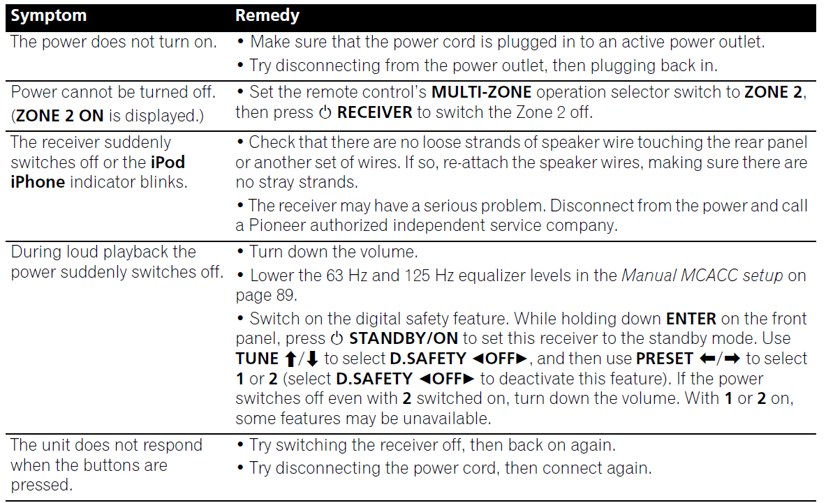
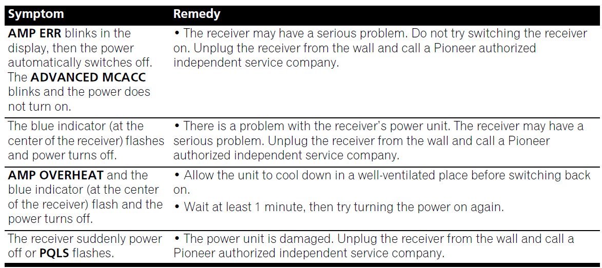
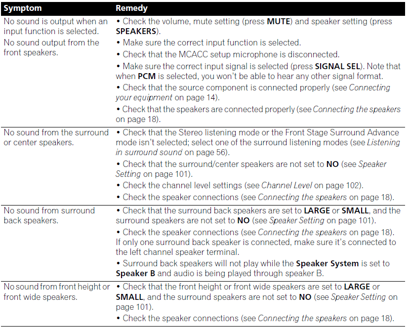
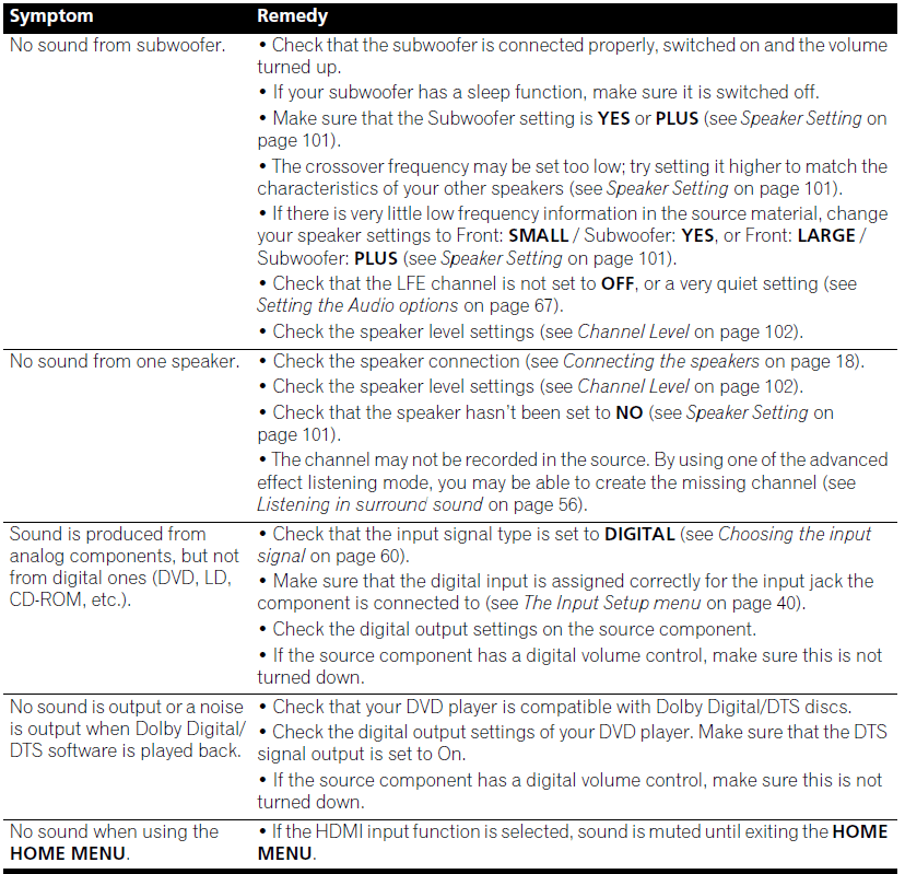
No sound 

For more manuals by Pioneer, visit ManualsLibraryy
Pioneer VSX 1020 Audio Video Multi Channel Receiver- FAQs
Does the Pioneer VSX-1021 support Bluetooth?
Yes, it supports Bluetooth with the optional AS-BT200 adapter. You can pair up to four Apple devices to stream music and create group playlists wirelessly.
What does resetting the receiver do?
Resetting the receiver can fix sound or picture issues such as pixilation or missing channels. You can reset it by pressing the red reset button or unplugging the unit for a few moments.
How much power does the Pioneer VSX receiver provide?
It delivers 140 watts per channel at 6 ohms (1 kHz, 1% THD), or 80 watts per channel at 8 ohms (20 Hz – 20 kHz, 0.08% THD).
How do I perform a hard factory reset?
Go to your device’s Settings, search for “Reset,” and tap Erase all data (factory reset) to restore default settings.
What happens when you reset an amplifier?
A factory reset clears all saved settings—including source, volume, and network preferences—returning the amplifier to its original state.
What is the role of a receiver in a sound system?
A receiver functions as an amplifier with a built-in radio tuner. It allows you to switch between inputs like a TV or CD player and powers your speakers.
Can I use my phone as a remote for the stereo?
Yes, using apps like QuickRemote, you can turn your smartphone into a universal remote to control your stereo and other home devices. Compatibility may vary by phone model.
What is the most powerful Pioneer receiver ever made?
The Pioneer SX-1980 is the most powerful receiver Pioneer has produced, and it’s considered one of the most powerful receivers ever made.
How many watts should my receiver have?
As a general rule, your receiver should provide at least 50 watts per channel. Larger speakers or high-volume listening may require more power for optimal performance.


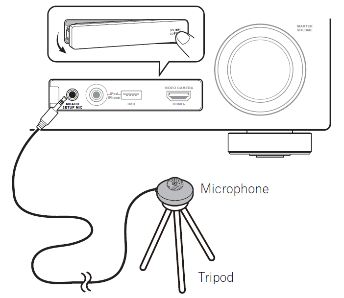 If you have a tripod, use it to place the microphone so that it’s about ear level at your normal listening position. If you do not have a tripod, use some other object to install the microphone.1 The Full Auto MCACC display appears once the microphone is connected.2
 The configuration shown on-screen should reflect the actual speakers you have.