
Suzuki 2006 Gsxr 600 Motorcycle
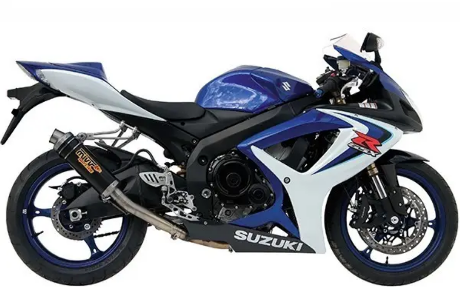
SUZUKI GSX-R750K6 (’06-MODEL)
 SERIAL NUMBER LOCATION
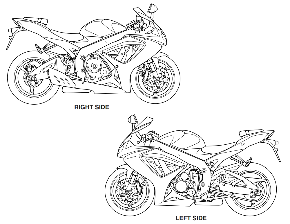
The frame serial number or VIN (Vehicle Identification Number) 1 is stamped on the right side of the steering head pipe. The engine serial number 2 is located on the right side of the crankcase. These numbers are required especially for registering the machine and ordering spare parts.

FUEL, OIL, AND ENGINE COOLANT RECOMMENDATION FUEL (FOR USA AND CANADA)
Use only unleaded gasoline of at least 90 pump octane (R/2 + M/2).
Gasoline containing MTBE (Methyl Tertiary Butyl Ether), less than 10% ethanol, or less than 5% methanol with appropriate cosolvents and corrosion inhibitor is permissible.
FUEL (FOR OTHER COUNTRIES)
Gasoline used should be graded 95 octane (Research Method) or higher. Unleaded gasoline is recommended.
ENGINE OIL (FOR USA)
Oil quality is a major contributor to your engine’s performance and life. Always select good-quality engine oil. Suzuki recommends the use of SUZUKI PERFORMANCE 4 MOTOR OIL or equivalent engine oil. Use of SF/SG or SH/SJ in API with MA in JASO.
Suzuki recommends the use of SAE 10W-40 engine oil. If SAE 10W-40 engine oil is not available, select an alternative according to the following chart.
ENGINE OIL (FOR OTHER COUNTRIES)
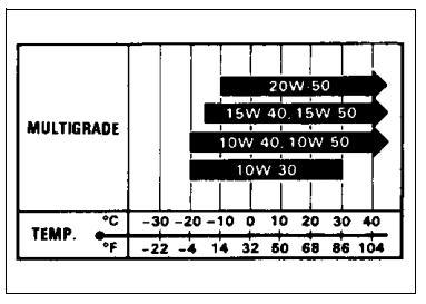
Oil quality is a major contributor to your engine’s performance and life. Always select good-quality engine oil. Use of SF/SG or SH/SJ in API with MA in JASO. Suzuki recommends the use of SAE 10W-40 engine oil. If SAE 10W-40 engine oil is not available, select an alternative according to the right chart.
BRAKE FLUID: Specification and classification: DOT 4
FRONT FORK OIL: Use fork oil SS-05 or an equivalent fork oil.
ENGINE COOLANT: Use an anti-freeze/engine coolant compatible with an aluminum radiator, mixed with distilled water only.
WATER FOR MIXING: Use distilled water only. Water other than distilled water can corrode and clog the aluminum radiator.
ANTI-FREEZE/ENGINE COOLANT: The engine coolant performs as a corrosion and rust inhibitor as well as an anti-freeze. Therefore, the engine coolant should be used at all times, even though the atmospheric temperature in your area does not go down
to the freezing point. Suzuki recommends the use of SUZUKI COOLANT anti-freeze/engine coolant. If this is not available, use an equivalent that is compatible with an aluminum radiator.
LIQUID AMOUNT OF WATER/ENGINE COOLANT
Solution capacity (total): Approx. 2,700 ml (2.9/2.4 US/Imp qt). For engine coolant mixture information, refer to the cooling system section on page 7-2.
BREAK-IN PROCEDURES
During manufacture, only the best possible materials are used, and all machined parts are finished to a very high standard, but it is still necessary to allow the moving parts to “BREAK-IN” before subjecting the engine to maximum stresses. The future performance and reliability of the engine depend on the care and restraint exercised during its early life. The general rules are as follows.
- Keep to these break-in engine speed limits:
- Initial 800 km ( 500 miles): Below 7 500 r/min
- Up to 1,600 km (1,000 miles): Below 11,000 r/min
- Over 1,600 km (1,000 miles): Below 15,000 r/min
- Upon reaching an odometer reading of 1,600 km (1,000 miles), you can subject the motorcycle to full throttle operation. However, do not exceed 15,000 r/min at any time.
CYLINDER IDENTIFICATION
The four cylinders of this engine are identified as No. 1, No. 2, No. 3, and No. 4 cylinders, as counted from left to right (as viewed by the rider on the seat).
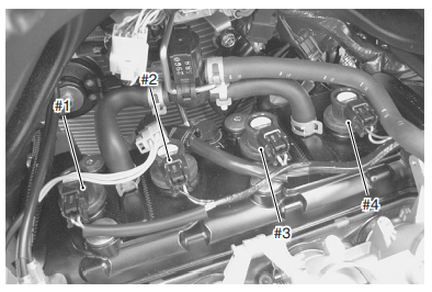
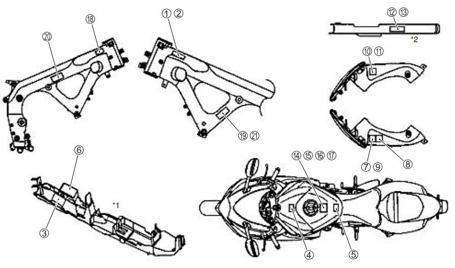
INFORMATION LABELS
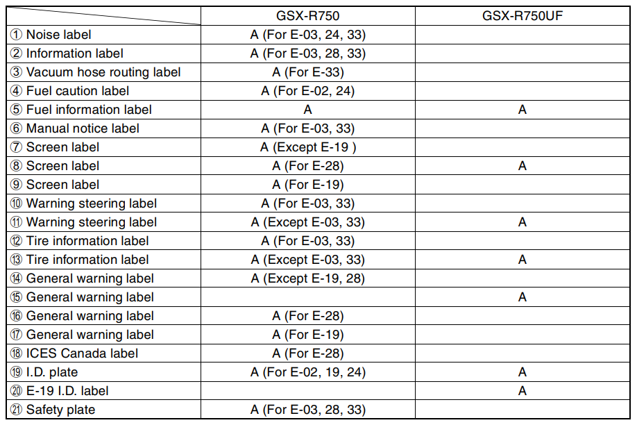
A: Attached
- Rear fender (front)
- Chain case
SPECIFICATIONS
DIMENSIONS AND DRY MASS
- Overall length ……………………………………………………………….. 2,040 mm (80.3 in)
- Overall width ………………………………………………………………… 715 mm (28.1 in)
- Overall height ……………………………………………………………….. 1 125 mm (44.3 in)
- Wheelbase …………………………………………………………………… 1,400 mm (55.1 in)
- Ground clearance………………………………………………………….. 130 mm (5.1 in)
- Seat height …………………………………………………………………… 810 mm (31.9 in)
- Dry mass ……………………………………………………………………… 164 kg (361 lbs) ………..E-33, 163 kg (359 lbs) ………..Others
ENGINE
- Type …………………………………………………………… Four-stroke, liquid-cooled, DOHC
- Number of cylinders ………………………………………………………. 4
- Bore…………………………………………………………………………….. 70.0 mm (2.756 in)
- Stroke………………………………………………………………………….. 48.7 mm (1.917 in)
- Displacement ……………………………………………………………….. 750 cm³ (45.8 cu. in)
- Compression ratio …………………………………………………………. 12.5 1
- Fuel system………………………………………………………………….. Fuel injection
- Air cleaner ……………………………………………………………………. Paper element
- Starter system ………………………………………………………………. Electric
- Lubrication system ………………………………………………………… Wet sump
- Idle speed…………………………………………………………………….. 1 200 ± 100 r/min
DRIVE TRAIN
- Clutch ………………………………………………………………………….. Wet multi-plate type
- Transmission………………………………………………………………… 6-speed constant mesh
- Gearshift pattern …………………………………………………………… 1-down, 5-up
- Primary reduction ratio …………………………………………………… 1.761 (74/42)
- Gear ratios, Low ……………………………………………………………. 2.785 (39/14)
- 2nd…………………………………………………………….. 2.052 (39/19)
- 3rd……………………………………………………………… 1.714 (36/21)
- 4th……………………………………………………………… 1.500 (36/24)
- 5th……………………………………………………………… 1.347 (31/23)
- Top…………………………………………………………….. 1.208 (29/24)
- Final reduction ratio……………………………………………………….. 2.647 (45/17)
- Drive chain ……………………………………………………………… RK525ROZ5Y, 116 links
CHASSIS
- Front suspension ……………………………. Inverted telescopic, coil spring, oil-damped
- Rear suspension ……………………………………………. Link type, coil spring, oil-damped
- Front fork stroke……………………………………………………………. 120 mm (4.7 in)
- Rear wheel travel………………………………………………………….. 130 mm (5.1 in)
- Steering angle………………………………………………………………. 27°
- Caster …………………………………………………………………………. 23° 45’
- Trail…………………………………………………………………………….. 97 mm (3.8 in)
- Turning radius………………………………………………………………. 3.4 m (11.2 ft)
- Front brake…………………………………………………………………… Disc brake, twin
- Rear brake …………………………………………………………………… Disc brake
- Front tire size …………………………………………….. 120/70 ZR 17 M/C (58 W), tubeless
- Rear tire size……………………………………………….. 180/55 ZR 17 M/C (73 W), tubeless
ELECTRICAL
- Ignition type………………………………………………. Electronic ignition (Transistorized)
- Ignition timing………………………………………………………… 8° B.T.D.C.at 1 200 r/min
- Spark plug………………………………………………. NGK CR9E or DENSO U27ESR-N
- Battery………………………………………………………………….. 12 V 36.0 kC (10 Ah)/10 HR
- Generator……………………………………………………………… Three-phase A.C. generator
- Main fuse …………………………………………………………………….. 30 A
- Fuse ……………………………………………………………………………. 10/10/15/15/10/10 A
- Headlight………………………………………………………. 12 V 55 W (H7) + 12 V 65 W (H9)
- Turn signal light…………………………………………………………….. 12 V 21 W
- License plate light …………………………………………………………. 12 V 5 W
- Brake light/Taillight………………………………………………………… LED
- Position light…………………………………………………………………. 12 V 5 W × 2
- Speedometer light…………………………………………………………. LED
- Tachometer light …………………………………………………………… LED
- Neutral indicator light …………………………………………………….. LED
- High beam indicator light ……………………………………………….. LED
- Turn signal indicator light ……………………………………………….. LED
- Fuel level indicator light …………………………………………………. LED
- Oil pressure/Coolant temperature/FI warning light ………………… LED
- Engine RPM indicator light……………………………………………… LED
- Immobilizer indicator light ……………………………………………. LED………E-02, 19, 24
CAPACITIES
- Fuel tank, including reserve………………………… 15.5 L (4.1/3.4 US/lmp gal), E-33 16.5 L (4.4/3.6 US/lmp gal)……Others
- Engine oil, oil change …………………………………………. 2 200 ml (2.3/1.9 US/Imp qt)
- with filter change ………………………………………….. 2 500 ml (2.6/2.2 US/lmp qt)
- overhaul………………………………………………………. 2 900 ml (3.1/2.6 US/lmp qt)
- Coolant……………………………………………………………………. 2.7 L (2.9/2.4 US/lmp qt)
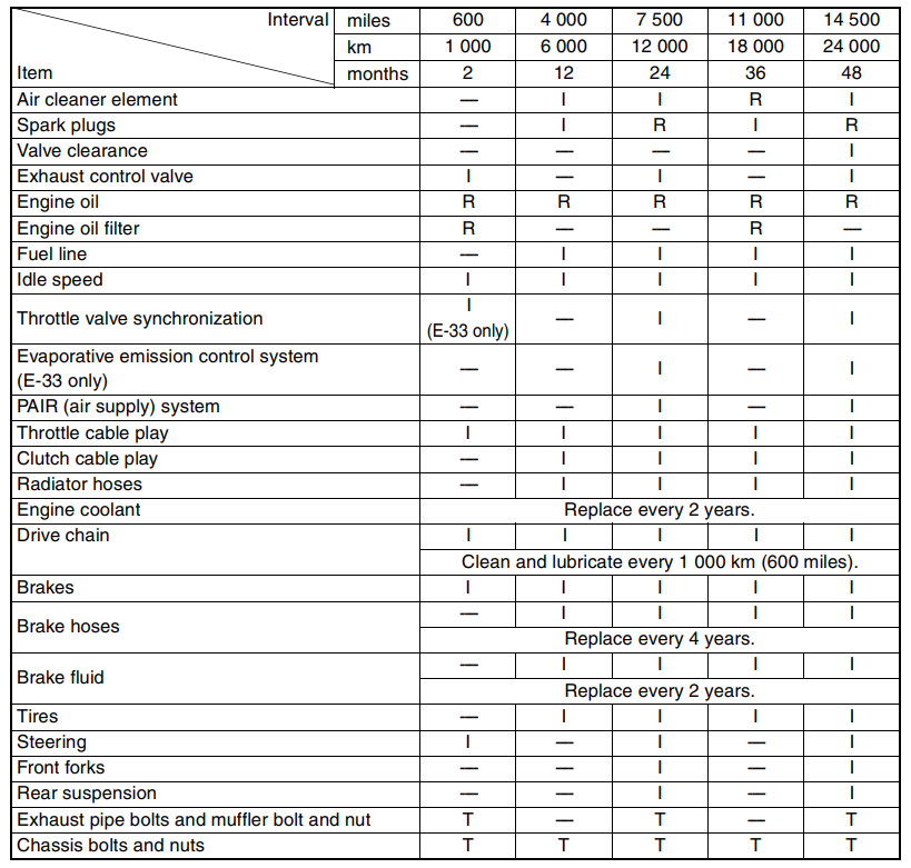
PERIODIC MAINTENANCE SCHEDULE
The chart below lists the recommended intervals for all the required periodic service work necessary to keep the motorcycle operating at peak performance and economy. Mileages are expressed in terms of kilometers, miles, and time for your convenience.
PERIODIC MAINTENANCE CHART
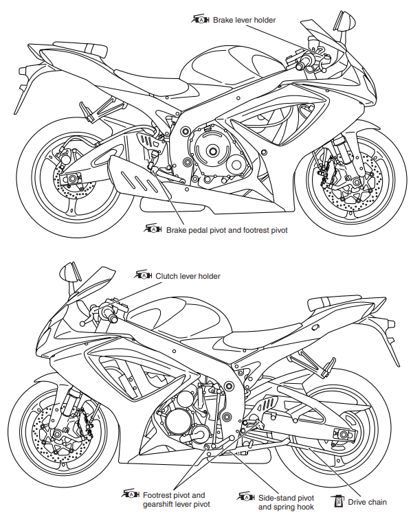
LUBRICATION POINTS
Proper lubrication is important for smooth operation and the long life of each working part of the motorcycle. Major lubrication points are indicated below.
MAINTENANCE AND TUNE-UP PROCEDURES
This section describes the servicing procedures for each item of the Periodic Maintenance requirement.s
AIR CLEANER
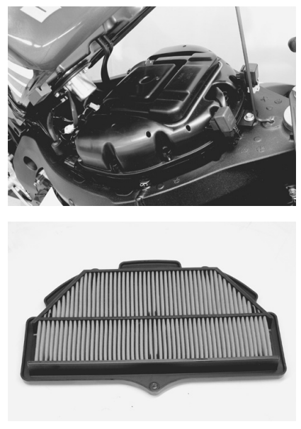
- Remove the front seat. (8-7)
- Lift and support the fuel tank. (5-3)
- Remove the air cleaner element by removing the screws.
- Remove the air cleaner element.
- Inspect the air cleaner element for clogging. If the air cleaner element is clogged with dust, replace the air cleaner element with a new one.
SPARK PLUG
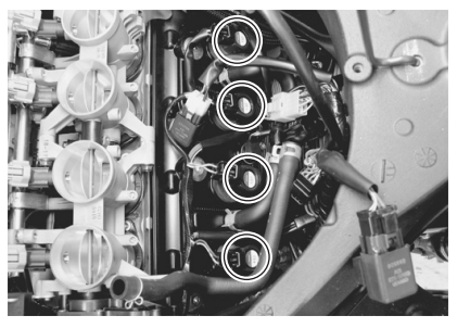
SPARK PLUG AND IGNITION COIL/PLUG CAP REMOVAL
- Remove the front seat. (8-7)
- Lift and support the fuel tank. (5-3)
- Remove the air cleaner box. (5-14)
- Disconnect all lead wire couplers from ignition coil/plug caps.
VALVE CLEARANCE
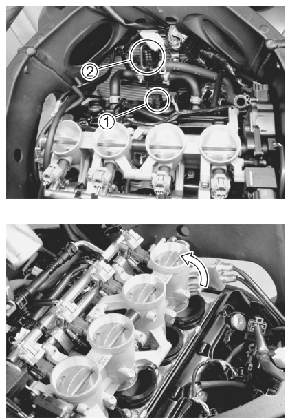
- Remove the right under cowling. (8-5)
- Lift and support the fuel tank. (5-3)
- Remove the air cleaner box. (5-14)
- Disconnect the CMP sensor coupler 1.
- Remove the PAIR control solenoid valve 2.
- Remove the spark plugs. (2-5)
- Loosen the throttle body clamp screws at the intake pipe side.
- Move the throttle body assembly.
- Move the radiator forward. (6-10)
- Remove the regulator/rectifier and horn. (3-6)
- Remove the cylinder head cover. (3-14)
VALVE CLEARANCE ADJUSTMENT
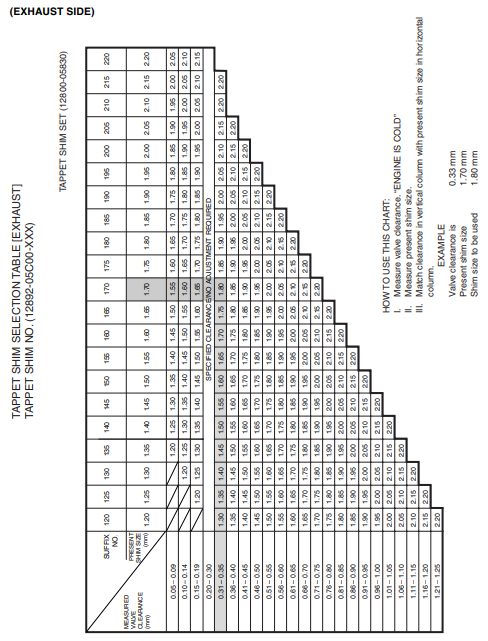
The clearance is adjusted by replacing the existing tappet shim with a thicker or thinner shim.
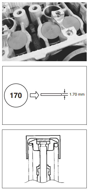
- Remove the intake or exhaust camshafts. (3-14)
- Remove the tappet and shim with your fingers or a magnetic hand.
- Check the figures printed on the shim. These figures indicate the thickness of the shim, as illustrated.
- Select a replacement shim that will provide a clearance within the specified range.
- For this adjustment, a total of 21 sizes of tappet shim are available, ranging from 1.20 to 2.20 mm in steps of 0.05 mm.
- Fit the selected shim to the valve stem end, with numbers toward the tappet. Be sure to check the shim size with a micrometer to ensure its size.
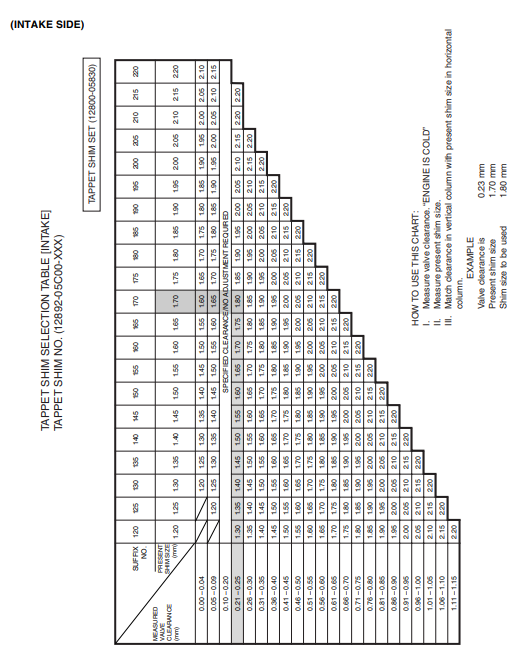
- Refer to the tappet shim selection table (2-10 and 11) for details.
CHASSIS BOLTS AND NUTS
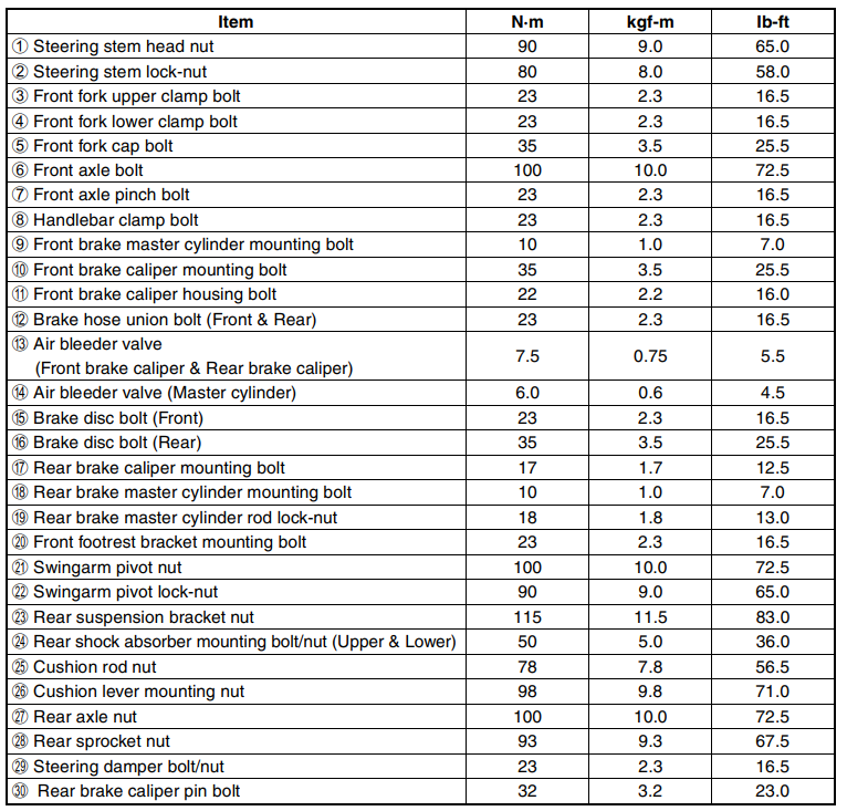
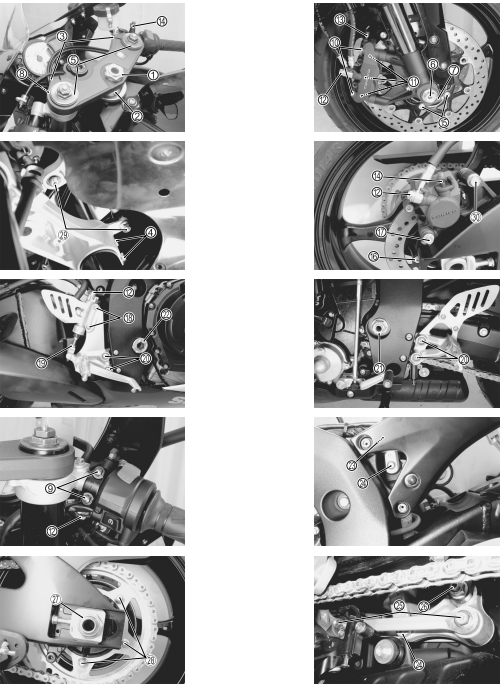
Check that all chassis bolts and nuts are tightened to their specified torque. (Refer to pages 2-31 for the locations of the following nuts and bolts on the motorcycle.)
ENGINE COMPONENTS REMOVABLE WITH ENGINE IN PLACE
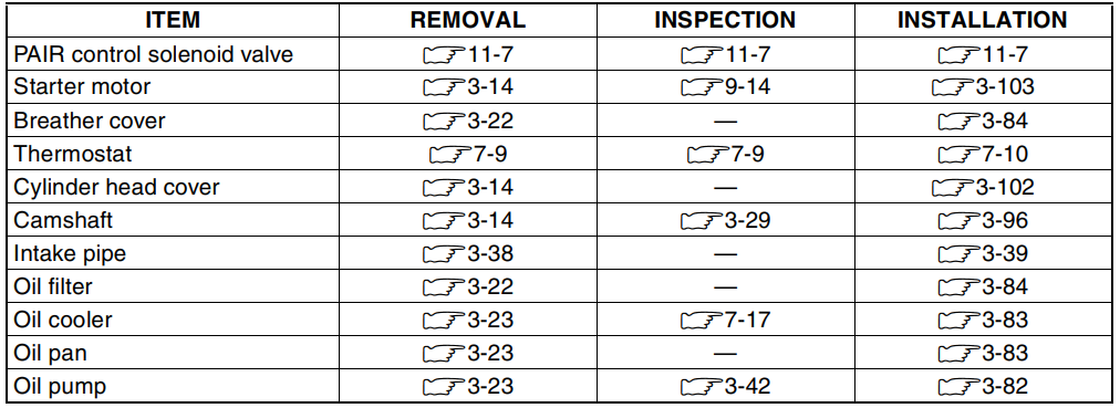
The parts listed below can be removed and reinstalled without removing the engine from the frame. Refer to the page listed in each section for removal and reinstallation instructions.
ENGINE CENTER
ENGINE RIGHT SIDE
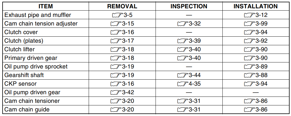
ENGINE LEFT SIDE

ENGINE REMOVAL AND INSTALLATION
ENGINE REMOVAL
Before taking the engine out of the frame, wash the engine using a steam cleaner. Engine removal is sequentially explained in the following steps. Reinstall the engine by reversing the removal procedure.
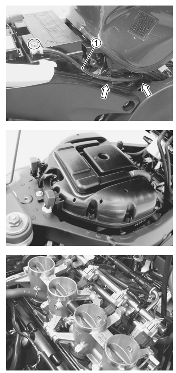
- Remove the undercowlings. (8-5)
- Lift and support the fuel tank. (5-3)
- Drain engine oil. (2-12)
- Drain engine coolant. (2-17)
- Disconnect the battery – lead wire 1.
- Remove the air cleaner box. (5-14)
- Remove the throttle body assembly. (5-15)
MOLYBDENUM OIL SOLUTION
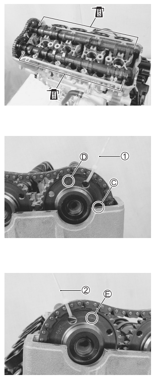
Before installing the camshaft, check that the tappets are installed correctly.
- Pull the cam chain lightly.
- The exhaust camshaft sprocket has an arrow marked “1” C. Turn the exhaust camshaft so that the arrow is aligned with the gasket surface of the cylinder head.
- Engage the cam chain with the exhaust camshaft sprocket.
- Bind the cam chain and sprocket with a proper clamp 1 to prevent the cam chain from disengaging while installing the camshaft journal holders.
- The other arrow marked “2” should now be pointing straight up. Starting from the roller pin that is directly above the arrow marked “2” D, count out 12 roller pins (from the exhaust camshaft side going towards the intake camshaft side).
- Engage the 12th roller pin E on the cam chain with the arrow marked “3” on the intake sprocket.
- Bind the cam chain and sprocket with a proper clamp 2 to prevent the cam chain from disengaging while installing the camshaft journal holders.
PRECAUTIONS IN SERVICING
When handling the parts or servicing the FI system, observe the following points for the safety of the system.
ELECTRICAL PARTS: CONNECTOR/COUPLER
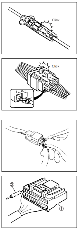
- When connecting a connector, be sure to push it in until a click is felt.
- With a lock-type coupler, be sure to release the lock when disconnecting, and push in fully to engage the lock when connecting.
- When disconnecting the coupler, be sure to hold the coupler body and do not pull the lead wires.
- Inspect each terminal on the connector/coupler for looseness or bending.
- Inspect each terminal for corrosion and contamination. The terminals must be clean and free of any foreign material that could impede proper terminal contact.
- Inspect each lead wire circuit for poor connection by shaking it
by hand lightly. If any abnormal condition is found, repair or replace. - When taking measurements at electrical connectors using a tester probe, be sure to insert the probe from the wire harness side (backside) of the connector/coupler.
ELECTRICAL CIRCUIT INSPECTION PROCEDURE
While there are various methods for electrical circuit inspection, described here is a general method to check for open and short circuits using an ohmmeter and a voltmeter.
OPEN CIRCUIT CHECK
Possible causes for the open circuits are as follows. As the cause can exist in the connector/coupler or terminal, they need to be checked carefully.
- Loose connection of the connector/coupler.
- Poor contact of terminal (due to dirt, corrosion or rust, poor contact tension, entry of foreign object, etc.).
- The wire harness is open.
- Poor terminal-to-wire connection.
- Disconnect the negative cable from the battery.
- Check each connector/coupler at both ends of the circuit being checked for loose connections. Also, check for condition of the coupler lock if equipped.
- Using a test male terminal, check the female terminals of the circuit being checked for contact tension. Check each terminal visually for poor contact (possibly
caused by dirt, corrosion, rust, entry of foreign objects, etc.). At the same time, check to make sure that each terminal is fully inserted in the coupler and locked.
If contact tension is not enough, rectify the contact to increase tension or replace it.
The terminals must be clean and free of any foreign material that could impede proper terminal contact. - Using the continuity inspection or voltage check procedure as described below, inspect the wire harness terminals for open circuit and poor connection. Locate abnormality, if any.
CAUTIONS IN SERVICING
CONNECTOR
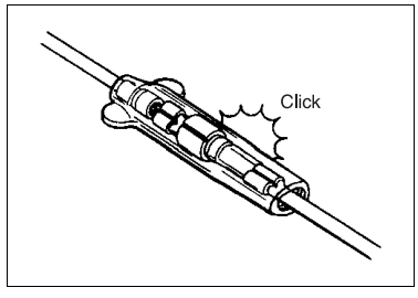
- When connecting a connector, be sure to push it in until a click is felt.
- Inspect the connector for corrosion, contamination and breakage in its cover.
COUPLER
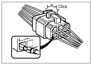
- With a lock-type coupler, be sure to release the lock when disconnecting, and push in fully to engage the lock when connecting.
- When disconnecting the coupler, be sure to hold the coupler
Itself and do not pull the lead wires. - Inspect each terminal on the coupler for being loose or bent.
- Inspect each terminal for corrosion and contamination.
CLAMP
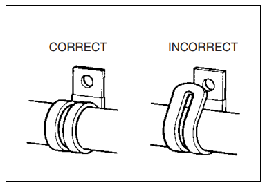
- Clap the wire harness at such positions as indicated in “WIRING HARNESS ROUTING”. (10-17 to -20)
- Bend the clamp properly so that the wire harness is clamped
securely. - In clamping the wire harness, use care not to allow it to hang
down. - Do not use wire or any other substitute for the band type
clamp
FUSE
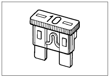
- When a fuse blows, always investigate the cause to correct it and then replace the fuse.
- Do not use a fuse of a different capacity.
- Do not use wire or any other substitute for the fuse.
SEMI-CONDUCTOR EQUIPPED PART
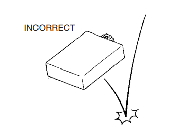
- Be careful not to drop the part with a semiconductor built i..
such as an ECM. - When inspecting this part, follow the inspection instructions strictly. Neglecting proper procedure may cause damage to this part.
BATTERY
- The MF battery used in this motorcycle does not require maintenance (e.g., electrolyte level inspection, distilled water
replenishment). - During normal charging, no hydrogen gas is produced. However, if the battery is overcharged, hydrogen gas may be produced. Therefore, be sure there are no fire or spark sources
(e.g., short circuit) nearby when charging the battery. - Be sure to recharge the battery in a well-ventilated and open
area. - Note that the charging system for the MF battery is different
from that of a conventional battery. Do not replace the MF
battery with a conventional battery.
FOR MORE MANUALS BY SUZUKI, VISIT MANUALSLIBRARYY
Suzuki 2006 Gsxr 600 Motorcycle-FAQs
What is the top speed of the 2006 GSX-R600?
The 2006 GSX-R600 has a top speed of ~175 mph (indicated) with a true speed of around 163 mph.
How many gears does the GSX-R600 have?
It features a 6-speed close-ratio transmission with optimized gear ratios for better acceleration and cornering performance.
Does the 2006 GSX-R600 have power modes?
No, the 2006 model does not have selectable power modes. Later models introduced Suzuki Drive Mode Selector (SDMS) with multiple mapping options.
What is the weight of the GSX-R600?
The curb weight is 412 lbs (187 kg).
What type of engine does the GSX-R600 have?
It has a 599cc liquid-cooled, inline-4 DOHC engine with fuel injection, designed for high-revving performance.
Is the 2006 GSX-R600 the fastest GSX-R model?
No, the fastest GSX-R model is the 2006 GSX-R1000, which holds a 0-60 mph time of 2.35 seconds.
What does “GSX-R” stand for?
GSX-R = Grand Sport eXperimental Racing, reflecting Suzuki’s high-performance sportbike lineage.
Does the 2006 GSX-R600 have a quick shifter?
No, the 2006 model does not come with a quick shifter (a feature added in later years).
What are the best tires for the GSX-R600?
Popular choices include:
Bridgestone S23 (road/track)
Michelin Power 6 (all-round performance)
Metzeler M9RR (grip-focused)
Does the GSX-R600 have ABS?
No, the 2006 model does not have ABS—it was introduced in later GSX-R models.

 SERIAL NUMBER LOCATION