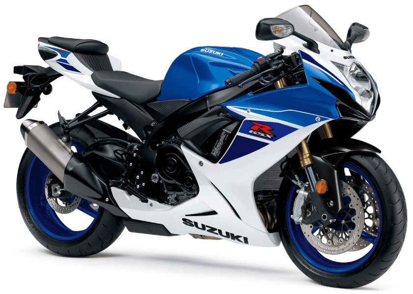
Suzuki GSX-R750 Sports Motorcycle Bike Service
HOW TO USE THIS MANUAL
TO LOCATE WHAT YOU ARE LOOKING FOR:
- The text of this manual is divided into sections.
- The section titles are listed in the GROUP INDEX.
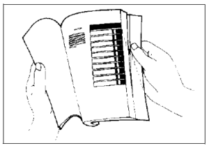
- Holding the manual as shown at the right will allow you to find the first page of the section easily.
- The contents are listed on the first page of each section to help you find the item and page you need.

COMPONENT PARTS AND WORK TO BE DONE
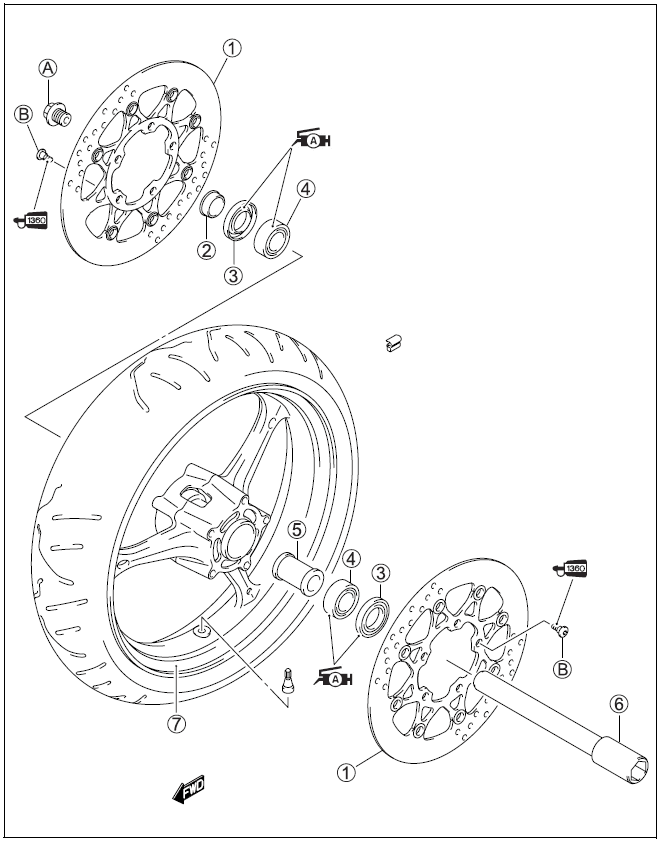
- Under the name of each system or unit, is its exploded view. Work instructions and other service information such as the tightening torque, lubricating points and locking agent points, are provided. Example: Front wheel

SUZUKI GSX-R750K6 (’06-MODEL)
FRONT FORK OIL
- Use fork oil SS-05 or an equivalent fork oil.
- ENGINE COOLANT
- Use an anti-freeze/engine coolant compatible with an aluminum radiator, mixed with distilled water only.
- WATER FOR MIXING
- Use distilled water only. Water other than distilled water can corrode and clog the aluminum radiator.
- ANTI-FREEZE/ENGINE COOLANT
- The engine coolant performs as a corrosion and rust inhibitor as well as an anti-freeze. Therefore, the engine coolant should be used at all times even though the atmospheric temperature in your area does not go down to freezing point.
- Suzuki recommends the use of SUZUKI COOLANT anti-freeze/engine coolant. If this is not available, use an equivalent that is compatible with an aluminum radiator.
CYLINDER IDENTIFICATION
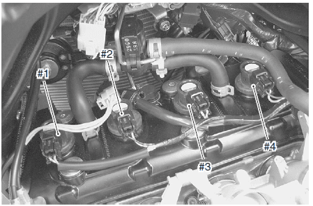
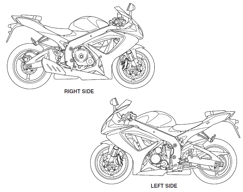
- The four cylinders of this engine are identified as No. 1, No. 2, No. 3 and No. 4 cylinder, as counted from left to right (as viewed by the rider on the seat.)

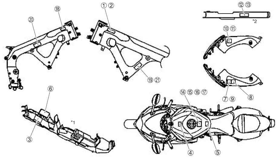
INFORMATION LABELS
| GSX-R750 | GSX-R750UF | |
| G) Noise label | A (For E-03, 24, 33) | |
| Cl Information label | A (For E-03, 28, 33) | |
| @ Vacuum hose routing label | A (For E-33) | |
| @ Fuel caution label | A (For E-02, 24) | |
| @ Fuel information label | A | A |
| @ Manual notice label | A (For E-03, 33) | |
| (!) Screen label | A (Except E-19 ) | |
| @ Screen label | A (For E-28) | A |
| ® Screen label | A (For E-19) | |
| ® Warning steering label | A (For E-03, 33) | |
| ® Warning steering label | A (Except E-03, 33) | A |
| @ Tire information label | A (For E-03, 33) | |
| ® Tire information label | A (Except E-03, 33) | A |
| ® General warning label | A (Except E-19, 28) | |
| ® General warning label | A | |
| ® General warning label | A (For E-28) | |
| ® General warning label | A (For E-19) | |
| (@ ICES Canada label | A (For E-28) | |
| @ I.D. plate | A (For E-02, 19, 24) | A |
| @ E-19 I.D. label | A | |
| @ Safety plate | A (For E-03, 28, 33) |
PERIODIC MAINTENANCE SCHEDULE
- The chart below lists the recommended intervals for all the required periodic service work necessary to keep the motorcycle operating at peak performance and economy. Mileages are expressed in terms of kilometers, miles and time for your convenience. IMPORTANT (For E-28): The periodic maintenance intervals and service requirements have been established in accordance with EPA regulations. Following these instructions will ensure that the motorcycle will not exceed emission standards and it will also ensure the reliability and performance of the motorcycle.https://manualslibraryy.com/dell-xps-13-9350-high-performance-laptop-service-manual/
- PERIODIC MAINTENANCE CHART
Interval Item
miles 600 4 000 7 500 11 000 14 500 km 1 000 6 000 12 000 18 000 24 000 months 2 12 24 36 48 Air cleaner element —- I I R I Spark plugs —- I R I R Valve clearance —- —- —- —- I Exhaust control valve I —- I —- I Engine oil R R R R R Engine oil filter R —- —- R —- Fuel line —- I I I I Idle speed I I I I I Throttle valve synchronization I (E-33 only)
—- I —- I Evaporative emission control system (E-33 only)
—- —- I —- I PAIR (air supply) system —- —- I —- I Throttle cable play I I I I I Clutch cable play —- I I I I Radiator hoses —- I I I I Engine coolant Replace every 2 years. Drive chain I I I I I Clean and lubricate every 1000 km (600 miles). Brakes I I I I I Brake hoses —- I I I I Replace every 4 years. Brake fluid —- I I I I Replace every 2 years. Tires —- I I I I Steering I —- I —- I Front forks —- —- I —- I Rear Suspension —- —- I —- I Exhaust pipe bolts and muffler bolts and nut T —- T —- T Chassis bolts and nuts T T T T T
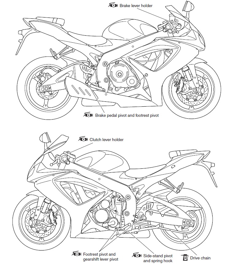
LUBRICATION POINTS
- Proper lubrication is important for smooth operation and long life of each working part of the motorcycle. Major lubrication points are indicated below

VALVE CLEARANCE
- Remove the right under the cowling. (8-5)
- Lift and support the fuel tank. (5-3)
- Remove the air cleaner box. (5-14)
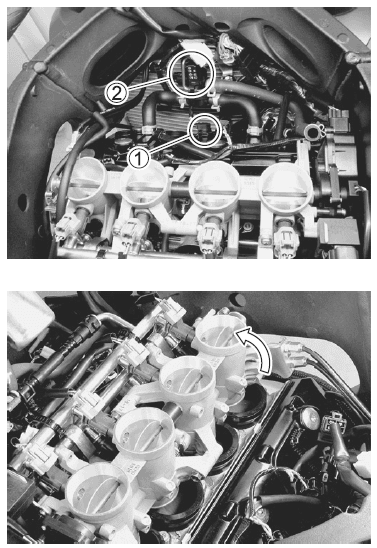
- Disconnect the CMP sensor coupler 1.
- Remove the PAIR control solenoid valve 2.
- Remove the spark plugs. (2-5)
- Loosen the throttle body clamp screws at the intake pipe side.
- Move the throttle body assembly.
- Move the radiator forward. (6-10)
- Remove the regulator/rectifier and horn. (3-6)
- Remove the cylinder head cover. (3-14)

VALVE CLEARANCE ADJUSTMENT
The clearance is adjusted by replacing the existing tappet shim with a thicker or thinner shim.
- Remove the intake or exhaust camshafts. (3-14)
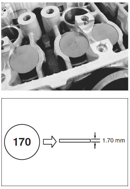
- Remove the tappet and shim by fingers or magnetic hand.
- Check the figures printed on the shim. These figures indicate the thickness of the shim, as illustrated.
- Select a replacement shim that will provide a clearance within the specified range. For the purpose of this adjustment, a total of 21 sizes of tappet shim are available ranging from 1.20 to 2.20 mm in steps of 0.05 mm. Fit the selected shim to the valve stem end, with numbers toward the tappet. Be sure to check shim size with a micrometer to ensure its size. Refer to the tappet shim selection table (2-10 and -11) for details

OIL FILTER REPLACEMENT
- Drain the engine oil as described in the engine oil replacement procedure.
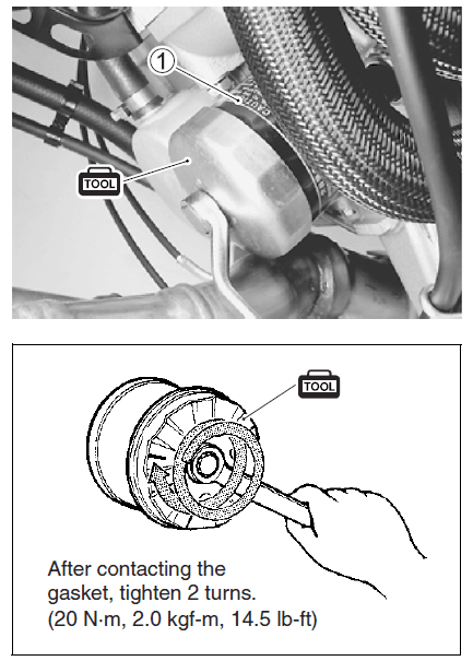
- Remove the oil filter 1 with the special tool.
- 09915-40610: Oil filter wrench
- Apply engine oil lightly to the gasket of the new oil filter before installation.
- Install the new oil filter. Turn it by hand until you feel that the oil filter gasket contacts the oil filter mounting surface. Then, tighten the oil filter two full turns (or to specified torque) with the special tool.

BRAKE
BRAKE FLUID LEVEL CHECK
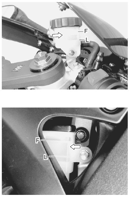
- Keep the motorcycle upright and place the handlebars straight.
- Check the brake fluid level relative to the lower limit lines on the front and rear brake fluid reservoirs.
- When the level is below the lower limit line, replenish with brake fluid that meets the following specifications.
- Specification and classification: DOT

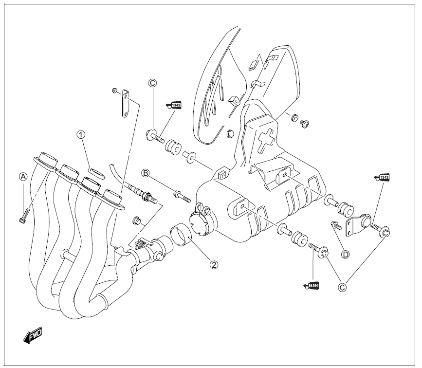
EXHAUST PIPE BOLT AND NUT
- Tighten the exhaust pipe bolts, muffler mounting bolt and nut to the specified torque

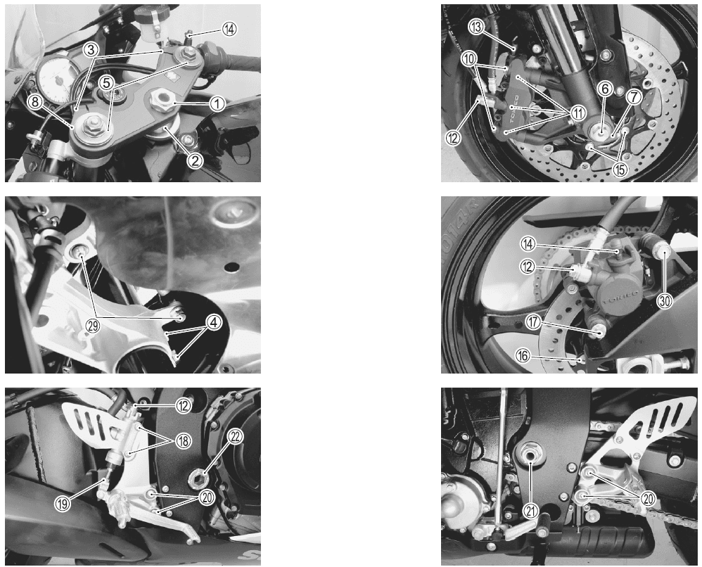
CHASSIS BOLTS AND NUTS
| Item | N·m | kgf-m | Ib-ft |
| CD Steering stem head nut | 90 | 9.0 | 65.0 |
| (2) Steering stem lock-nut | 80 | 8.0 | 58.0 |
| @ Front fork upper clamp bolt | 23 | 2.3 | 16.5 |
| @ Front fork lower clamp bolt | 23 | 2.3 | 16.5 |
| @ Front fork cap bolt | 35 | 3.5 | 25.5 |
| @ Front axle bolt | 100 | 10.0 | 72.5 |
| (!) Front axle pinch bolt | 23 | 2.3 | 16.5 |
| @ Handlebar clamp bolt | 23 | 2.3 | 16.5 |
| ® Front brake master cylinder mounting bolt | 10 | 1.0 | 7.0 |
| ® Front brake caliper mounting bolt | 35 | 3.5 | 25.5 |
| ® Front brake caliper housing bolt | 22 | 2.2 | 16.0 |
| @ Brake hose union bolt (Front & Rear) | 23 | 2.3 | 16.5 |
| ® Air bleeder valve (Front brake caliper & Rear brake caliper) | 7.5 | 0.75 | 5.5 |
| ® Air bleeder valve (Master cylinder) | 6.0 | 0.6 | 4.5 |
| ® Brake disc bolt (Front) | 23 | 2.3 | 16.5 |
| ® Brake disc bolt (Rear) | 35 | 3.5 | 25.5 |
| ® Rear brake caliper mounting bolt | 17 | 1.7 | 12.5 |
| (@ Rear brake master cylinder mounting bolt | 10 | 1.0 | 7.0 |
| @ Rear brake master cylinder rod lock-nut | 18 | 1.8 | 13.0 |
| ® Front footrest bracket mounting bolt | 23 | 2.3 | 16.5 |
| @ Swingarm pivot nut | 100 | 10.0 | 72.5 |
| @ Swingarm pivot lock-nut | 90 | 9.0 | 65.0 |
| @ Rear suspension bracket nut | 115 | 11.5 | 83.0 |
| @ Rear shock absorber mounting bolt/nut (Upper & Lower) | 50 | 5.0 | 36.0 |
| @ Cushion rod nut | 78 | 7.8 | 56.5 |
| @ Cushion lever mounting nut | 98 | 9.8 | 71.0 |
| ® Rear axle nut | 100 | 10.0 | 72.5 |
| @ Rear sprocket nut | 93 | 9.3 | 67.5 |
| ® Steering damper bolt/nut | 23 | 2.3 | 16.5 |
| ® Rear brake caliper pin bolt | 32 | 3.2 | 23.0 |
COMPRESSION PRESSURE CHECK
- The compression pressure reading of a cylinder is a good indicator of its internal condition. The decision to overhaul the cylinder is often based on the results of a compression test. Periodic maintenance records kept at your dealership should include compression readings for each maintenance service.
COMPRESSION PRESSURE SPECIFICATION
| Standard | Limit | Difference |
| 1 300 – 1 700 kPa (13 – 17 kg/cm2, 185 – 242 psi) | 1 000 kPa (10 kg/cm2, 148 psi) | 200 kPa (2 kg/cm2, 28 psi) |
Low compression pressure can indicate any of the following conditions:
- Excessively worn cylinder walls
* Worn piston or piston rings
* Piston rings stuck in grooves
* Poor valve seating
* Ruptured or otherwise defective cylinder head gasket
Overhaul the engine in the following cases:
- Compression pressure in one of the cylinders is 1 000 kPa (10 kg/cm2, 148 psi) and less.
- The difference in compression pressure between any two cylinders is 200 kPa (2 kg/cm2, 28 psi) and more.
- All compression pressure readings are below 1 300 kPa (13 kg/cm2, 185 psi) even when they measure 1000 kPa (10 kg/cm2, 148 psi) and more.
CYLINDER HEAD AND VALVE
VALVE AND VALVE SPRING DISASSEMBLY
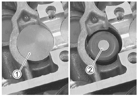
- Remove the tappet 1 and shim 2 by fingers or magnetic hand.

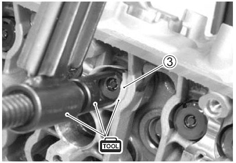
- Install the special tool 3 between the valve spring and cylinder head.

- Using the special tools, compress the valve spring and remove the two cotter halves from the valve stem
TRANSMISSION
DRIVESHAFT REMOVAL
DISASSEMBLY
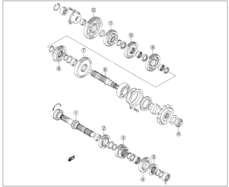
Disassemble the countershaft and driveshaft. Pay attention to the following points:
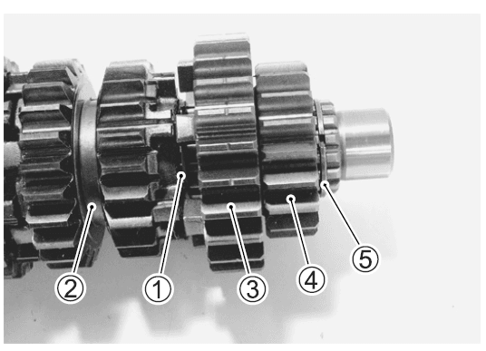
- Remove the 6th drive gear snap ring 1 from its groove and slide it towards the 3rd/4th drive gear 2.

- Slide the 6th 3 and 2nd 4 drive gears toward the 3rd/4th drive gears 2, then remove the 2nd drive gear circlip 5.

| G) | Countershaft/1st drive gear |
| (2) | 5th drive gear |
| @ | 3rd/4th drive gears |
| @ | 6th drive gear |
| @ | 2nd drive gear |
| @ | Driveshaft |
| (l) | 2nd driven gear |
| @ | 6th driven gear |
| ® | 3rd driven gear |
| ® | 4th driven gear |
| @ | 5th driven gear |
| @ | 1st driven gear |
| ® | Engine sprocket nut |
For more manuals by Suzuki visit, ManualsLibraryy
Suzuki GSX-R750 Sports Motorcycle Bike Service-FAQs
How much power does the Suzuki GSX-R750 produce?
The GSX-R750 delivers 127.9 hp (95.4 kW) at 12,600 rpm and 55.7 lb-ft (75.5 Nm) of torque at 11,100 rpm. It has a wet weight of 194.1 kg (428 lbs).
What is the warranty on a Suzuki GSX-R?
The GSX-R1000 comes with a 12-month unlimited mileage limited warranty. Additional coverage and benefits are available through the Suzuki Extended Protection (SEP) program.
How often should I change the oil in my GSX-R750?
The first oil change should be done at 600 miles or two months. After that, oil should be replaced every 4,000 miles or once a year, along with the oil filter.
Is the GSX-R750 a fast motorcycle?
Yes, the GSX-R750 is a high-performance sportbike known for its speed, lightweight design, and responsive chassis. It delivers an engaging ride without excessive electronics interfering with the experience.
What is the fuel tank capacity of the Suzuki GSX-R750?
The Suzuki GSX-R750 has a fuel tank capacity of 12 liters, offering a balance between range and performance.
What does GSX-R stand for?
GSX-R stands for “Grand Sport eXperimental – Racing,” reflecting Suzuki’s focus on high-performance motorcycles designed for racing and sport riding.
How reliable is a Suzuki motorcycle?
Suzuki motorcycles are known for their reliability, offering durable performance backed by strong engineering and efficient designs.
Where is the GSX-R750 manufactured?
Suzuki produces all GSX-R series motorcycles entirely in Japan, ensuring high-quality manufacturing standards.
How often should motorcycle engine oil be changed?
Engine oil should generally be replaced every 3,000 to 5,000 kilometers to maintain peak performance and prevent engine wear over time.


