
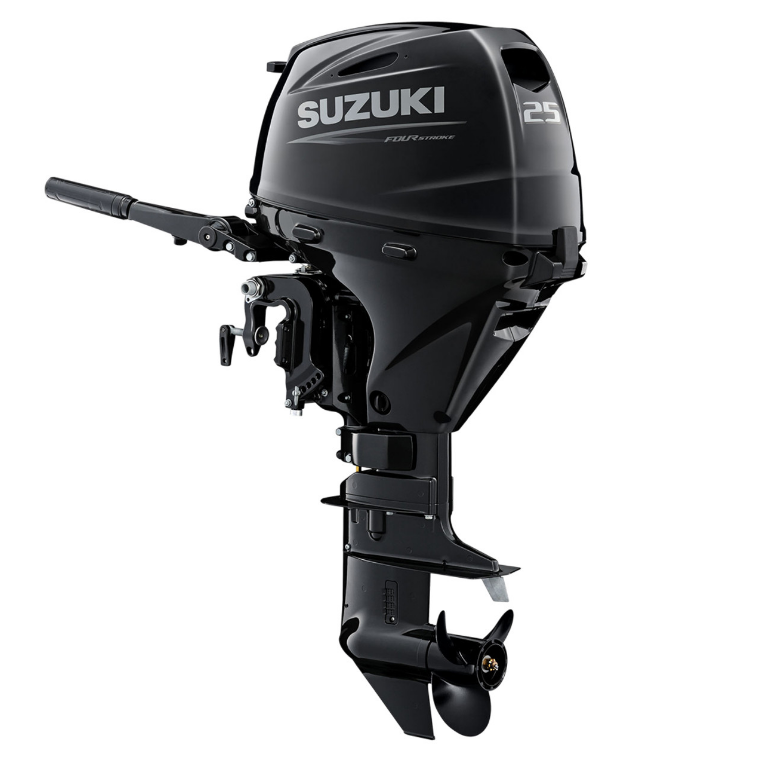
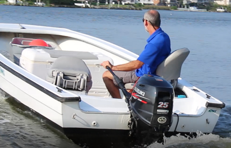
Suzuki DF-25 Outboard Motor
HOW TO USE THIS MANUAL
TO LOCATE WHAT YOU ARE LOOKING FOR:
- The text of this manual is divided into sections.
- The section titles are listed on the previous page in a GROUP INDEX. Select the section needed for reference.
- Holding the manual as shown at the right will allow you to find the first page of the section easily.
- The first page of each section lists a table of contents to easily locate the item and page you need.
GENERAL INFORMATION
WARNING/CAUTION/NOTE
Please read this manual and follow its instructions carefully. To emphasize special information, the symbol and the words WARNING, CAUTION and NOTE have special meanings. Pay special attention to the messages highlighted by these signal words.
WARNING: Indicates a potential hazard that could result in death or injury.
CAUTION: Indicates a potential hazard that could result in motor damage.
NOTE: Indicates special information to make maintenance easier or instructions clearer.
Please note, however, that the warnings and cautions contained in this manual cannot possibly cover all potential hazards relating to the servicing, or lack of servicing, of the outboard motor. In addition to the WARNING and CAUTION stated, you must also use good judgement and observe basic mechanical safety principles
GENERAL PRECAUTIONS
WARNING
- Proper service and repair procedures are important for the safety of the service mechanic and the safety and reliability of the outboard motor.
- To avoid eye injury, always wear protective goggles when filing metals, working on a grinder, or doing other work, which could cause flying material particles.
- When 2 or more persons work together, pay attention to the safety of each other.
- When it is necessary to run the outboard motor indoors, make sure that exhaust gas is vented outdoors.
- When testing an outboard motor in the water and on a boat, ensure that the necessary safety equipment is on board. Such equipment includes : flotation aids for each person, fire extinguisher, distress signals, anchor, paddles, bilge pump, first-aid kit, emergency starter rope, etc.
- When working with toxic or flammable materials, make sure that the area you work in is wellventilated and that you follow all of the material manufacturer’s instructions.
- Never use gasoline as a cleaning solvent.
- To avoid getting burned, do not touch the engine, engine oil or exhaust system during or
shortly after engine operation. - Oil can be hazardous. Children and pets may be harmed from contact with oil. Keep new and used oil away from children and pets. To minimize your exposure to oil, wear a long sleeve shirt and moisture-proof gloves (such as dishwashing gloves) when changing oil. If oil contacts your skin, wash thoroughly with soap and water. Launder any clothing or rags if wet with oil. Recycle or properly dispose of used oil.
- After servicing fuel, oil/engine cooling system and exhaust system, check all lines and fittings related to the system for leaks.
- Carefully adhere to the battery handling instructions laid out by the battery supplier.
CAUTION
- If parts replacement is necessary, replace the parts with Suzuki Genuine Parts or their equivalent.
- When removing parts that are to be reused, keep them arranged in an orderly manner so that they may be reinstalled in the proper order and orientation.
- Be sure to use special tools when instructed.
- Make sure that all parts used in assembly are clean and also lubricated when specified.
- When use of a certain type of lubricant, bond, or sealant is specified, be sure to use the specified type.
- When removing the battery, disconnect the negative cable first and then the positive cable.
- When reconnecting the battery, connect the positive cable first and then the negative cable.
- When performing service to electrical parts, if the service procedures do not require using battery power, disconnect the negative cable at the battery.
- Tighten cylinder head and case bolts and nuts, beginning with larger diameter and ending with smaller diameter. Always tighten from inside to outside diagonally to the specified tightening torque.
- Whenever you remove oil seals, gaskets, packing, O-rings, locking washers, locking nuts, cotter pins, circlips, and certain other parts as specified, always replace them with new. Also, before installing these new parts, be sure to remove any left over material from the mating surfaces.
- Never reuse a circlip. When installing a new circlip, take care not to expand the end gap larger than required to slip the circlip over the shaft. After installing a circlip, always ensure that it is completely seated in its groove and securely fitted.
- Use a torque wrench to tighten fasteners to the torque values when specified. Remove grease or oil from screw / bolt threads unless a lubricant is specified.
- After assembly, check parts for tightness and operation.
- To protect the environment, do not unlawfully dispose of used motor oil, other fluids, and batteries.
- To protect the Earth’s natural resources, properly dispose of used motor parts.
IDENTIFICATION NUMBER LOCATION
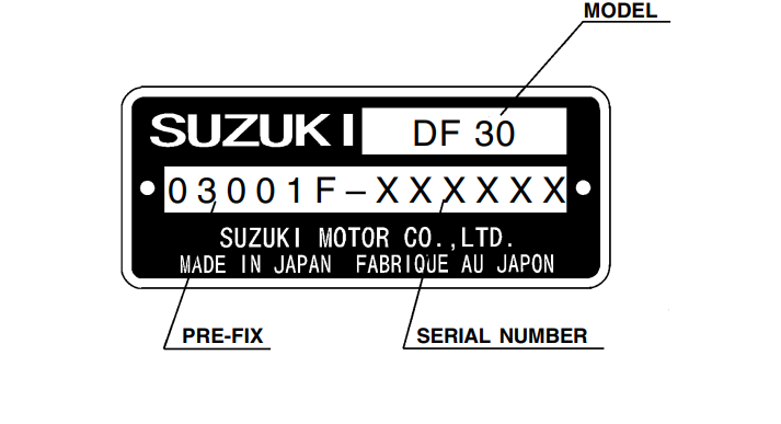
MODEL, PRE-FIX, SERIAL NUMBER
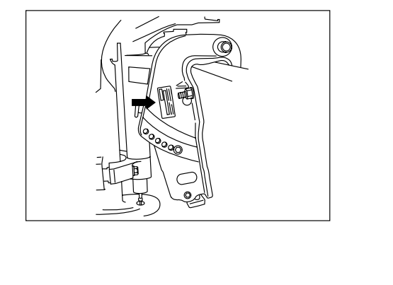
The MODEL, PRE-FIX and SERIAL NUMBER of motor are stamped on a plate attached to the clamp bracket.
Example
ENGINE SERIAL NUMBER
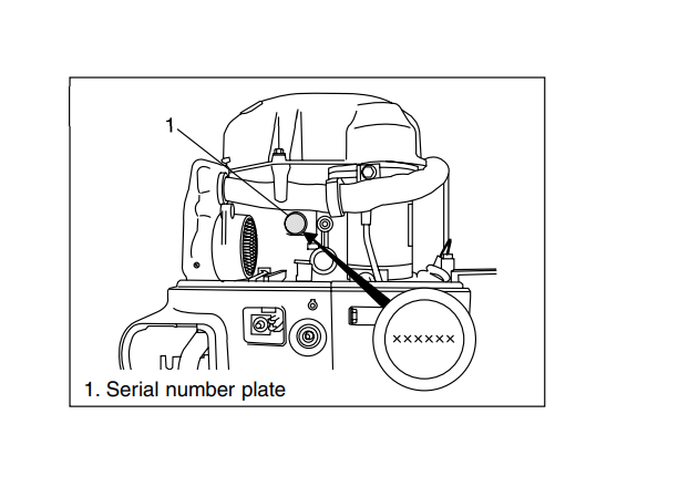
A second engine serial number plate is pressed into a bosson the crankcase
FUEL AND OIL GASOLINE RECOMMENDATION
Suzuki highly recommends that you use alcohol – free unleaded gasoline with a minimum pump octane rating of 87 (R+M / 2 method) or 91 (Research method). However, blends of unleaded gasoline and alcohol with equivalent octane content may be used. Allowable maximum blend of a single additive (not combination) : 5% Methanol, 10% Ethanol, 15% MTBE
CAUTION If leaded gasoline is used, engine damage may result. Use only unleaded gasoline.
ENGINE OIL
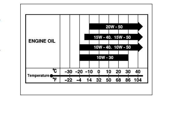
Use only oils that are rated SE, SF, SG, SH, or SJ under the API (American Petroleum Institute) classification system.
The viscosity rating should be SAE 10W-40. If an SAE 10W-40 motor oil is not available, select an alternative according to the chart at right.
ENGINE BREAK-IN
The first 10 hours are critically important to ensure correct running of either a brand new motor or a motor that has been reconditioned or rebuilt. How the motor is operated during this time will have direct bearing on its life span and long-term durability.
Break-in period : 10 hours
WARM-UP RECOMMENDATION
Allow sufficient idling time (more than 5 minutes) for the engine to warm up after cold engine starting.
THROTTLE RECOMMENDATION
NOTE: Avoid maintaining a constant engine speed for an extended period at any time during the engine break-in by varying the throttle position occasionally.
- FIRST 2 HOURS
- For first 15 minutes, operate the engine in-gear at idling speed.
- During the remaining 1 hour and 45 minutes, operate the engine in-gear at less than 1/2 (half) throttle (3000 r/min).
NOTE: The throttle may be briefly opened beyond the recommended setting to plane the boat, but must be reduced to the recommended setting immediately after planing.
- NEXT 1 HOUR
Operate the engine in-gear at less than 3/4 (three-quarter) throttle (4000 r/min). - LAST 7 HOURS
Operate the engine in-gear at desired engine speed. However, do not operate continuously at full throttle for
more than 5 minutes.
PROPELLERS
An outboard motor is designed to develop its rated power within a specified engine speed range. The maximum rated power delivered by the DF25 / 30 models are shown below.

If the standard propeller fails to meet the above requirement, use another pitch propeller to hold the engine speed within the range specified above.
Propeller selection chart
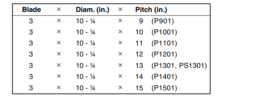
CAUTION: Installing a propeller with pitch either too high or too low will cause incorrect maximum engine speed, which may result in severe damage to the motor.
SPECIFICATIONS

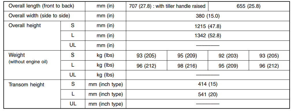
DIMENSIONS & WEIGHT
PERFORMANCE

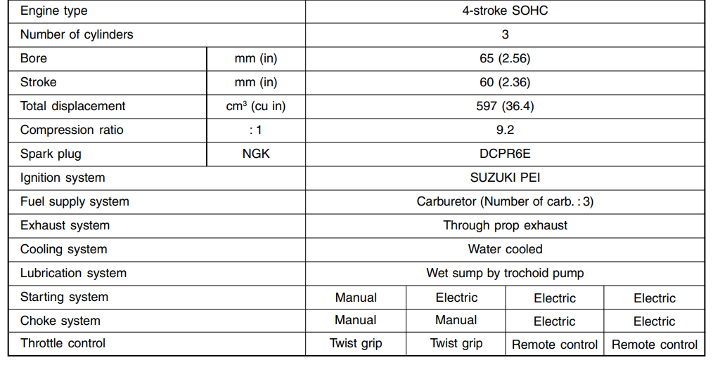
POWERHEAD

FUEL & OIL

BRACKET

LOWER UNIT
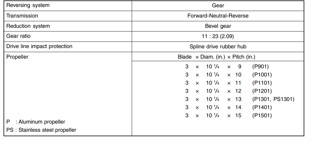
PERIODIC MAINTENANCE SCHEDULE
The chart below lists the recommended intervals for all the required periodic service work necessary to keep the motor operating at peak performance and economy. Maintenance intervals should be judged by number of hours or months, whichever comes first.
NOTE: More frequent servicing should be performed on outboard motors that are used under severe conditions.
PERIODIC MAINTENANCE CHART
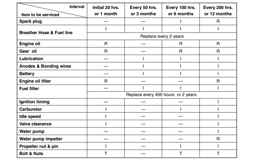
I : Inspect and clean, adjust, lubricate, or replace, if necessary T : Tighten R : Replace
MAINTENANCE AND TUNE-UP PROCEDURES
This section describes the servicing procedures for each of the periodic maintenance requirements
ENGINE OIL / ENGINE OIL FILTER ENGINE OIL LEVEL CHECK
Inspect oil level before every use.
- Place the outboard motor upright on a level surface.
- Remove the motor cover.
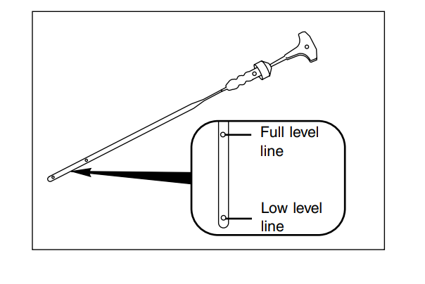
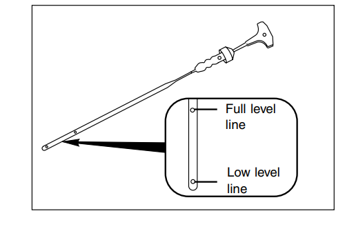
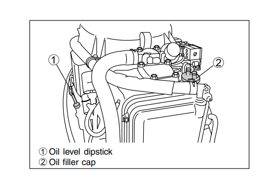
- Remove the oil level dipstick and wipe it clean.
- Insert it fully into the dipstick hole, then remove it to check oil leve

- (5) Oil level should be between the full level line (Max.) and low level line (Min.)
If the level is low, add recommended oil to full level line.
Recommended oil :
- 4 stroke motor oil
- API classification SE, SF, SG, SH, SJ.
- Viscosity rating SAE 10 W-40.
ENGINE OIL CHANGE / ENGINE OIL FILTER REPLACEMENT
ENGINE OIL Change initially after 20 hours (1 month) and every 100 hours (6 months) thereafter.
ENGINE OIL FILTER Replace initially after 20 hours (1 month) and every 200 hours (12 months) thereafter.
NOTE:
- Engine oil should be changed while the engine is warm.
- When replacing the engine oil filter, change engine oil at the same time.
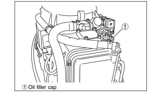
- Place the outboard motor upright on a level surface.
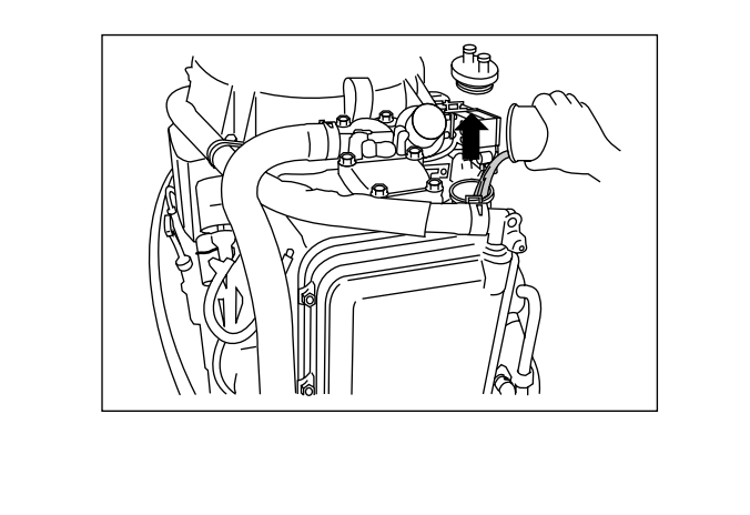
- Remove the oil filler cap

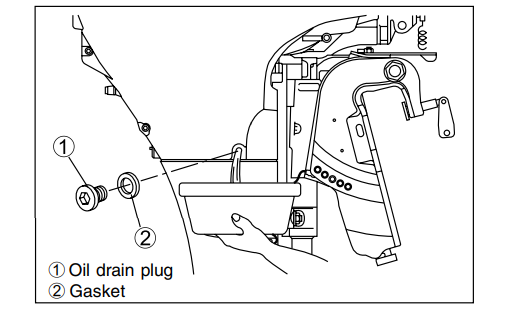
- Place a container under the engine oil drain plug.
- Remove the engine oil drain plug and gasket to drain engine oil.
- ENGINE OIL FILTER REPLACEMENT
NOTE: For engine oil change only, go to step 6. To replace the engine oil filter :- Remove the PORT side lower cover. (See page 8-2)
- Using oil filter wrench, loosen the oil filter.

09915-47340 : Oil filter wrench
NOTE: Before fitting new oil filter, be sure to oil O-ring
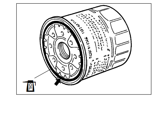
- Screw new filter on by hand until the filter O-ring contacts the Mounting surface.
- Tighten the filter 3/4 turn from the point of contact with the mounting surface using an oil filter wrench.
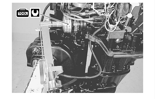
Engine oil filter : 14 N.m (1.4 kg-m, 10.0 lb.-ft.), 3/4 turn.
- Install the PORT side lower cover.
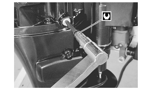
- Install the gasket and the oil drain plug. Tighten the engine oil drain plug to the specified torque.
Engine oil drain plug : 13 N.m (1.3 kg-m, 9.5 lb.-ft.)
CAUTION Do not re-use gasket. Always replace with a new gasket
- Pour recommended engine oil into the oil filler opening, then install the oil filler cap.
Engine oil amounts
- Oil change only : 3.0 L (3.2 / 2.6 US / Imp. qt)
- Oil filter change : 3.2 L (3.4 / 2.8 US / Imp. qt)
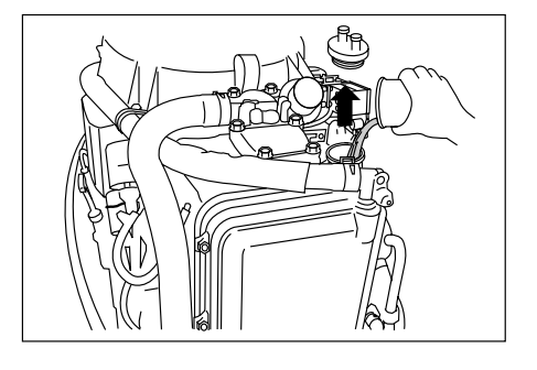
- Start the engine and allow it to run for several minutes at
idle speed. Check oil filter for oil leakage. Turn off the engine and wait for approx. two minutes, then re-check the engine oil level.
GEAR OIL
Change initially after 20 hours (1 month) and every 100 hours (6 months) thereafter.
- Place the outboard motor upright on a level surface.
- Place a container under the lower unit.
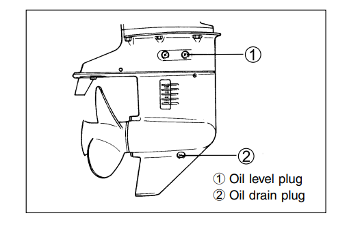
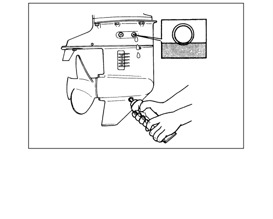
- Remove the lower gear oil drain plug before the gear oil level plug and drain the gear oil.

- ) Fill with the recommended gear oil through the oil drain hole until oil just starts to flow out from the oil level hole. Gear oil amount : 230 ml ( 7.8 / 8.1 US / Imp. oz) Recommended oil : Suzuki Outboard Motor Gear Oil or SAE # 90 Hypoid gear oil

- Install the oil level plug before removing the oil filler tube from the drain hole.
- Install the oil drain plug
CAUTION Do not re-use gaskets. Always use a new gasket.
NOTE: To avoid insufficient injection of gear oil, check the gear oil level 10 minutes after doing the procedure in the step (6). If the oil level is low, slowly inject the gear oil up to the correct level.
LUBRICATION
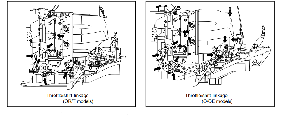
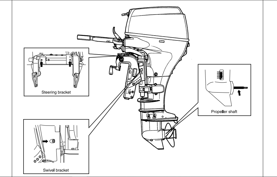
Inspect every 50 hours (3 months).
Apply Suzuki Water Resistant Grease to the following points.
SPARK PLUG
- Inspect every 100 hours (6 months).
- Replace every 200 hours (12 months).
Standard spark plug : NGK DCPR6E
CAUTION Only resistor (R) type spark plugs must be used with this engine. Using a non-resistor spark plug will cause ignition system malfunctions.
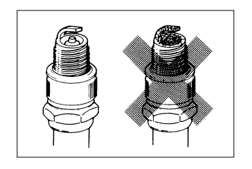
CARBON DEPOSIT
Check for a carbon deposit on the spark plug bases. If carbon is present, remove it with a spark plug cleaning machine or by carefully using a pointed tool.
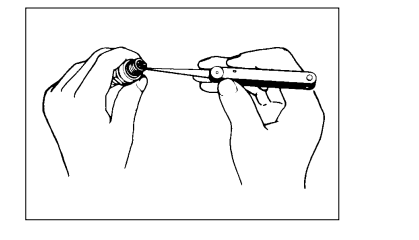
SPARK PLUG GAP
Use a thickness gauge to measure for correct spark plug gap. Adjust to within the specified range if the gap is out of specification.
Spark plug gap : 0.8 – 0.9 mm (0.031 – 0.035 in.)
09900-20803 : Thickness gauge
CONDITION OF ELECTRODE
Check the electrode for a worn or burnt condition. If it is extremely worn or burnt, replace the spark plug. Also, be sure to replace the plug if it has a broken insulator, damaged thread, etc.
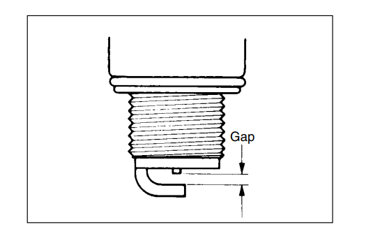
CAUTION Confirm the thread size and reach when replacing the plug. If the reach is too short, carbon will be deposited on the threaded portion of the plug hole resulting in possible engine damage.
Spark plug : 18 N . m (1.8 kg-m, 13.0 lb.-ft.)
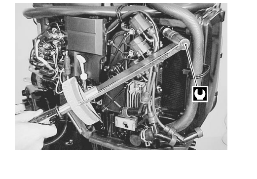
VALVE CLEARANCE
Inspect initially after 20 hours (1 month) and every 200 hours (12 months) thereafter
CHECKING AND ADJUSTING VALVE CLEARANCE Checking
- Remove following parts :
- Engine side lower cover (see page 8-2)
- Recoil starter (Manual start model)
- Flywheel cover (Electric start model)
- Spark plugs

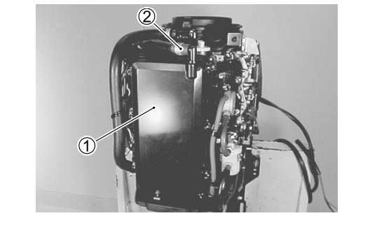
- Remove breather hose 2 from cylinder head cover 1.
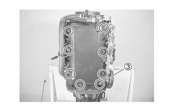
- Remove the eight (8) bolts 3 securing the cylinder head cover to the cylinder head and remove cylinder head cover1.
- Rotate crankshaft clockwise to bring each piston to Top Dead Center (TDC) on compression stroke.

CAUTION Dead Center (TDC) on compression stroke. Rotate crankshaft clockwise to prevent water pump impeller damage.
NOTE :
- Piston must be at its TDC on compression stroke to check or adjust valve clearance.
- Valve clearance specification is for COLD engine condition.
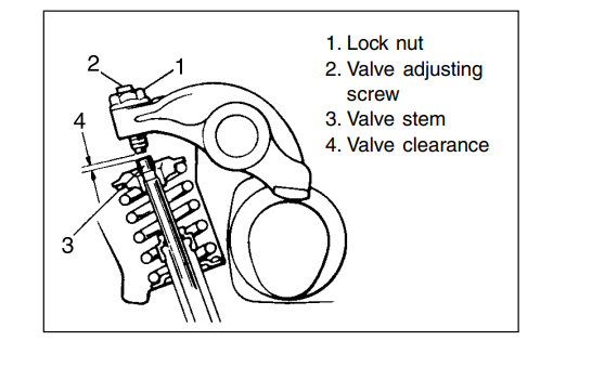
- Measure valve clearance by inserting thickness gauge between valve stem end and valve adjusting screw on rocker arm.

09900-20803 : Thickness gauge
- Valve clearance (cold engine condition) :
- IN. 0.13 – 0.17 mm (0.005 – 0.007 in.)
- EX. 0.13 – 0.17 mm (0.005 – 0.007 in.)
If out of specification, adjust valve clearance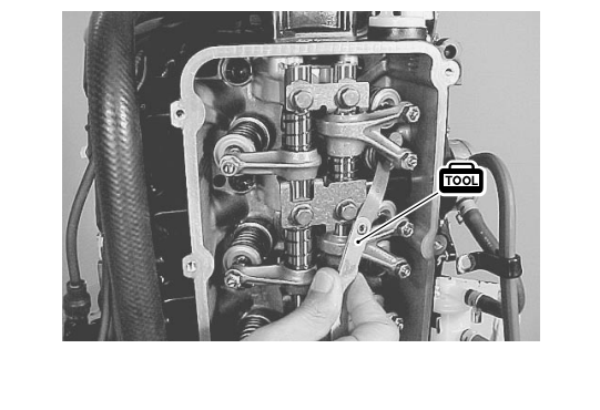
Adjustment
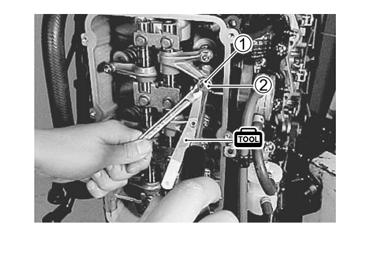
- Loosen valve adjusting lock nut 1.
- Turn valve adjusting screw 2 to bring valve clearance to within the specification.
09900-20803 : Thickness gauge
- Tighten valve adjusting lock nut 1 to specified torque while holding valve adjusting screw 2.
Valve adjusting lock nut : 11 N.m (1.1 kg-m, 8.0 lb.-ft.)
Recheck valve clearance Reassembly
After checking and adjusting all valves, reverse removal procedure for installation.
- Install the cylinder head cover. (See page 7-9)
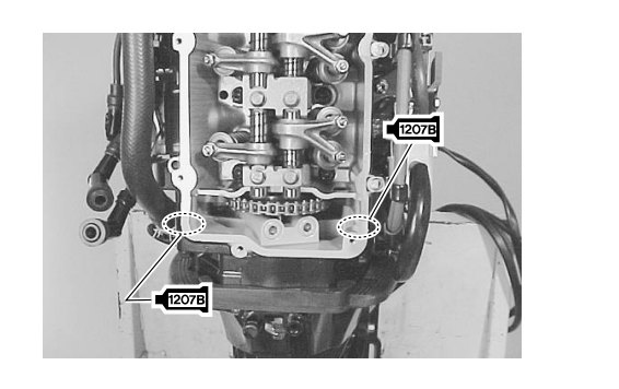
NOTE :Examine cylinder head cover gasket for damage. Always replace gasket if sealing performance is suspect.
- Tighten cylinder head cover bolts to specification.
Cylinder head cover bolt : 11 N.m (1.1 kg-m, 8.0 lb.-ft.)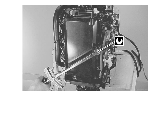
For more manuals by Suzuki, visit ManualsLibraryy
How often should I change the engine oil?
Change the oil for the first time after the initial 20 hours of operation (break-in period). After that, change the oil every 100 hours or once a year, whichever comes first.
What is the difference between the DF25 and the DF25A?
The DF25A model features an updated design and an intelligent fuel management system, making it up to 15% more fuel-efficient than the previous DF25 model.
What is the fuel mixture for this outboard?
The Suzuki DF-25 is a 4-stroke engine and uses straight, unleaded gasoline. It does not require any oil to be mixed with the fuel.
What is the correct spark plug gap?
The proper spark plug gap for the DF25A is 0.8 – 0.9 mm (0.031 – 0.035 in). Always check the gap with a feeler gauge when installing new plugs.
How often should the water pump impeller be changed?
It is recommended to inspect and replace the water pump impeller every year to ensure the engine is being cooled correctly and to prevent overheating.
How long can a Suzuki DF-25 outboard last?
With proper maintenance and care, a Suzuki outboard can last between 1,500 to 2,000 hours. For the average recreational boater, this translates to 15-20 years or more of reliable service.
How do I know if my outboard is overheating?
Key signs of overheating include:
A noticeable change in water output from the tell-tale (pee-hole stream).
A visible decrease in engine power.
Steam mixed with the exhaust.
The engine’s overheating warning alarm sounding.

 Reassembly