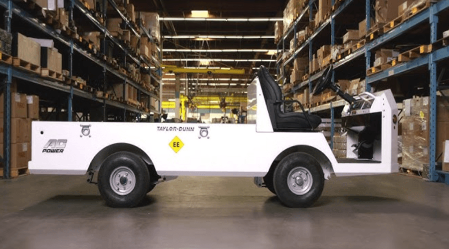
Taylor-Dunn B0-150-00 LoadMaster Electric Golf Cart
Introduction
Conventions
Symbols and/or words used to define Dangers, Warnings, Cautions, and Notices are found throughout this manual. The “Words” in this context will be referred to as “Signal words.” The words defined here as “signal words” may be used elsewhere in the text of this document without being a signal word. When used as a signal word, the signal word will be enclosed in a solid rectangle with a white background (example below).
Signal Words and Their Definitions:
- DANGER: This signal word will be accompanied by the safety alert symbol (see below). “DANGER” will indicate a hazard that, if not avoided, WILL result in death or serious bodily injury to yourself, the operator or passengers of the vehicle, or people in the immediate area of the vehicle.
- WARNING: This signal word will be accompanied by the safety alert symbol (see below). “WARNING” will indicate a hazard that, if not avoided, may result in death or serious bodily injury to yourself, the operator or passengers of the vehicle, or people in the immediate area of the vehicle.
- CAUTION: This signal word will be accompanied by the safety alert symbol (see below). “CAUTION” will indicate a hazard that, if not avoided, may result in minor or moderate injury to yourself, the operator or passengers of the vehicle, or people in the immediate area of the vehicle.
- NOTICE: This signal word will not be accompanied by the safety alert symbol. “NOTICE” will indicate a condition that if not avoided may result in property damage. “Property” is defined as the vehicle, components in the vehicle and/or the surrounding area such as buildings, other vehicles, etc.
Safety Messages
Important information notifying you of any conditions that may result in hazards to yourself, persons nearby, and/ or hazards to the vehicle will be presented in a text box with a black border and may include a signal word (see above). To the right is an example of a safety message. The safety message may include additional warning icons representing the type of hazard. The following is a list of these icons and what they represent. These icons may also be included on the various warning and information decals applied to the vehicle.
RESPONSIBILITIES
Of the Owner…
The owner of this or any Taylor-Dunn vehicle is responsible for the overall maintenance and repairs of the vehicle, as well as the training of operators. The owner is also responsible for operator training per the following federal regulations:
- ANSI/ITSDF 56.8-2006 Personnel and Burden Carriers: Part II, Paragraph 6.2a.
- ANSI/ITSDF 56.9 – 2007 Safety Standard for Operator Controlled Industrial Tow Tractors: Part
II, paragraph 4.11. - Code of Federal Regulations (CFR) Title 29, Subtitle B, Chapter Xvii OSHA, Part 1910.178
Powered Industrial Trucks (2011): 1910.178, Section (l).
Per OSHA Regulation, 29 CFR 1910.178 Powered Industrial Truck Operator Training, the owner must keep a record of conducted training and maintenance performed on the vehicle.
Of the Operator…
A vehicle shall not be operated until the operator has successfully completed an operator training course
provided by the owner of the vehicle. The operator is responsible to be sure that the vehicle is operated only on authorized roads, highways, and installations.
The operator is responsible for confirming that all passengers are properly seated and using the available restraints. The operator is responsible for the safe operation of the vehicle, preoperational, and operational checks on the vehicle, and the reporting of any problems to service and repair personnel.
Of the Passengers …
The passengers are responsible for remaining fully seated, keeping their hands, arms, and legs inside the vehicle at all times. Each passenger shall be fully aware of the vehicle’s operation. All forms of recklessness are to be avoided.
HOW TO IDENTIFY YOUR VEHICLE
This manual is valid only for the serial numbers listed on the front cover. If the ending serial number is blank, then this manual was for current production vehicles when printed. If you did not receive this manual with the vehicle, you should confirm this manual is valid for your serial number at the Taylor-Dunn website. The locations of the model and serial numbers are shown in the illustrations below: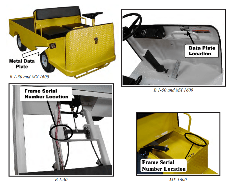
Service/Maintenance Guidelines
READ ME FIRST-MAINTENANCE GUIDELINES AND GENERAL INSTRUCTIONS
- Read the operator’s manual before operating this vehicle.
- Avoid fire hazards and have fire protection equipment present in the work area.
- Conduct vehicle performance checks in an authorized area where safe clearance exists.
- Ventilate the work area properly.
- Regularly inspect and maintain the following systems in a safe working condition: brakes, steering mechanisms, speed and directional control mechanisms, warning devices, lights, governors, guards, and safety devices.
- Inspect and maintain battery limit switches, protective devices, electrical conductors, and connections in conformance with Taylor-Dunn’s® recommended procedures.
- Keep the vehicle in a clean condition to minimize fire hazards and facilitate the detection of loose or defective parts.
- Do not use an open flame to check the level or leakage of the battery electrolyte.
- Do not use open pans of fuel or flammable fluids for cleaning parts.
- Only properly trained and authorized technicians should perform maintenance or repairs to this vehicle.
REPLACEMENT PARTS
Using Non-OEM Replacement Components
To maintain peak performance, always use original Taylor-Dunn replacement parts intended for use on your vehicle. Taylor-Dunn components are designed and tested for use on specific Taylor-Dunn model vehicles. Only use the correct Taylor-Dunn replacement components for your Taylor-Dunn vehicle.
Electrical Components
Electrical components not tested by Taylor-Dunn (or intended for use on other Taylor-Dunn vehicles) may have unanticipated interaction and/or interference with the vehicle’s control system resulting in unsafe vehicle operation or damage to the electrical system.
Mechanical Components
Mechanical components not tested by Taylor-Dunn (or from other model Taylor-Dunn vehicles) may have an undesirable effect on the operation of the vehicle, result in additional frame stress, or stress other components resulting in premature failure or an unsafe condition. Due to the unknown properties of non-Taylor-Dunn tested components or from components not originally equipped on the vehicle, we cannot approve their use in a Taylor-Dunn vehicle.
PM Schedule
DAILY VISUAL INSPECTION
The following items shall be inspected once every day before the vehicle is put into service:
- External frame damage (body).
- Operation of all lights and warning alarms.
- Proper operation of all instrument panel gauges and warning lights.
- Smooth and proper operation of seat belts (if equipped).
- Brake fluid level.
- Tire tread or sidewall damage.
- Proper operation of adjustable seat mechanisms (if equipped).
Smooth and proper operation of all controls as but not limited to:
- Throttle pedal
- Brake pedal
- Parking brake
- Steering
- Horn Etc.
Proper operation of all locking mechanisms as but not limited to:
- Hood latches
- Cargo box’s
- Cab doors Etc.
Proper operation of all interlocking switches as but not limited to:
- Ignition switch
- Operator presence switch
- Brake interlock switch. Etc.
MAINTENANCE SCHEDULE
A PM Checklist is available and was included on the documentation CD that was provided with your vehicle. The document number is PM-0005.
Maintenance Guidelines for Severe Duty Applications
This maintenance schedule is based on the average typical application. If the vehicle is operated under
“severe conditions”, service procedures shall be conducted more frequently than specified. The frequency of service under severe conditions is determined by the use of the vehicle. The owner/operator must evaluate the operating environment to determine the increase in maintenance frequency.
In addition, the entire vehicle shall be inspected monthly for signs of damage. The following list is meant as a guide and is not all-inclusive of a “severe duty” application.
- Operation in excess of 100 hours per month.
- Extreme temperature.
- Bumpy, dusty, or ill-maintained roads.
- Excessively wet areas.
- Corrosive or contaminated areas.
- Frequent loading of the vehicle at/near capacity.
Tool List
Tool List
The tools shown here are generic for servicing Taylor-Dunn vehicles. Not all tools will be required for servicing this vehicle.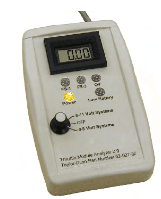
- 62-027-32: Throttle Module Analyzer Tests the throttle module in or out of the vehicle.

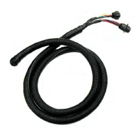
- 75-089-00: Throttle Module Test Harness Used in conjunction with a volt meter to test the throttle module. The module must be installed in a working control system. Note: Part # 62-027-31 includes instructions

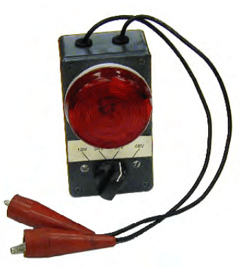
- 62-027-00: Test Light Used for testing electrical circuits. Switchable for 12, 24, 36, 48 volt systems.
Required to complete troubleshooting provided in the vehicle service manuals.
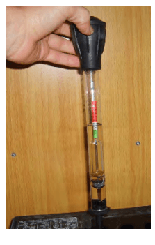
- 77-200-00: Hydrometer Used for testing battery electrolyte. Illustration is of a typical hydrometer, actual hydrometer type may vary.

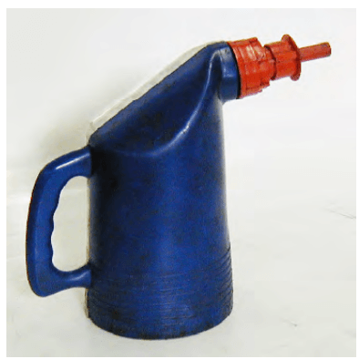
- 77-201-00: Battery Filler Used to safely add water to batteries. Equipped with splash guard and auto shut off when the cell is full.

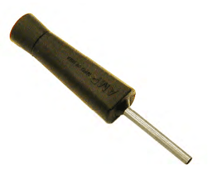
- 70-440-55: Pin Removing Tool Removes pin from Amp circular harness connectors.

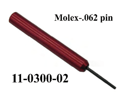
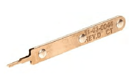
- Molex # 11-300-02: Pin Removing Tool Removes 0.062 diameter pins from Molex rectangular harness connectors. Not available from Taylor-Dunn. Purchase from any local electronics distributor.

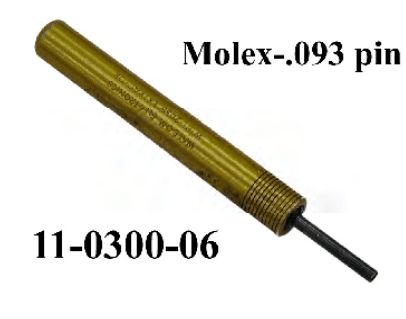
- Molex # 11-300-06: Pin Removing Tool Removes 0.093 diameter pins from Molex rectangular harness connectors. Not available from Taylor-Dunn. Purchase from any local electronics distributor.

- 75-442-55: Pin Removing Tool Removes pins from Molex Mini-Fit harness connectors.
TROUBLESHOOTING GUIDE
This is a general troubleshooting guide for various mechanical faults. Refer to the electrical troubleshooting chapter for checking the electronic motor control system. This list is provided as a guide only. It is not all-inclusive of causes that may result in a specific symptom.
| Symptom | Suspect Component or System | Action |
| Steering Pulls Left or Right | Front end out of alignment | Realign front end |
| Low tire pressure | Inspect tire pressure | |
| Difficult Steering | Lack of lubrication | Lubricate steering linkages |
| Damaged or worn steering components | Inspect all steering components | |
| Low tire pressure | Inspect tire pressure | |
| Excessive Play in Steering | Damaged or worn steering linkages | Inspect steering linkages |
| Loose steering linkages | Tighten all hardware | |
| Loose steering wheel | Inspect steering wheel nut | |
| Loose front spring hardware | Tighten all hardware | |
| Soft and/or Low Brake Pedal | Air in brake lines | Bleed brake system |
| Master cylinder fluid level low | Fill master cylinder and bleed system | |
| Brake pedal linkage out of adjustment | Adjust linkages | |
| Hard Brake Pedal | Faulty master cylinder | Inspect master cylinder |
| Lack of Braking Power | Contaminated brake pads | Replace brake pads |
| Worn brakes | Replace brakes | |
| Air in brake lines | Bleed brake system | |
| Brakes Dragging | Brake pedal linkage out of adjustment | Adjust linkages |
| Faulty master cylinder | Inspect master cylinder | |
| Faulty brake caliper | Inspect brake calipers | |
| Debris in brakes | Inspect brakes | |
| Parking brake applied | Release parking brake, inspect linkage | |
| Low Power or Running Slow | Faulty or discharged battery | Test battery and charge |
| Brakes dragging | Inspect brake system | |
| Fault in motor control system | Refer to motor control fault codes | |
| Noise, Front End | Loose wheel nuts | Tighten all hardware |
| Damaged or worn wheel bearings | Inspect wheel bearings | |
| Damaged, worn, or debris in brakes | Inspect brakes | |
| Loose components | Tighten all hardware | |
| Damaged or worn suspension mounts | Inspect suspension | |
| Noise, Rear End | Loose wheel nuts | Tighten all hardware |
| Damaged or worn internal transaxle components | Inspect transaxle | |
| Damaged or worn suspension mounts | Inspect suspension |
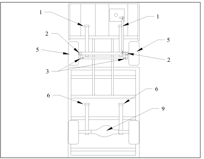
LUBRICATION DIAGRAM
DISASSEMBLE
Disassembling and reassembling involve removing and replacing the left and right steering knuckles and king pin bushings. Refer to the following sections for information regarding these procedures:
Replace the Steering Knuckle Replace the King Pins and Bushings
NOTE: The front axle does not have to be removed unless the axle beam must be replaced. Refer to Front Axle Removal and Installation for information regarding removing the front axle.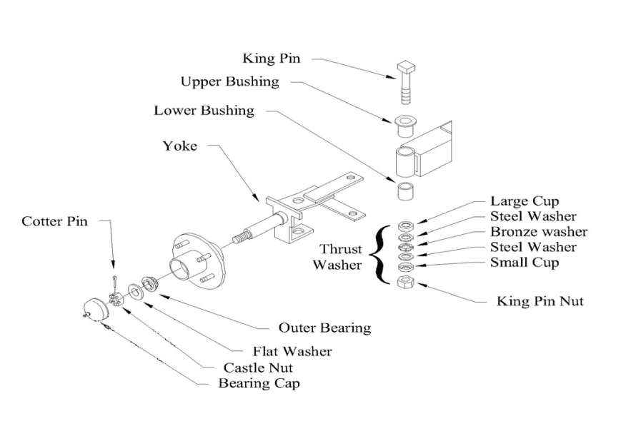
INSPECT FRONT WHEEL BEARINGS
- Raise the front of the vehicle and support it with jack stands.
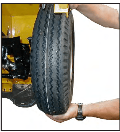
- Grab the top and bottom of the tire/wheel assembly. Feel for any movement or play while pulling and pushing on the top and bottom of the tire. Any movement or play is an indication of loose wheel bearings.

- Spin the front wheel(s) by hand. The wheel should stop spinning in no more than 2-revolutions. A wheel that continues to spin freely is an indication of a loose wheel bearing.
Note: Refer to the Adjust Front Wheel Bearings section for detailed information regarding the
proper adjustment of the wheel bearings. - Spin the wheel(s) and listen for any grinding noise. Any noise may be an indication of worn or
damaged wheel bearings.
Note: Refer to the Replace Front Wheel Bearings section for information regarding the replacement of the wheel bearings. - Lower the vehicle.
- Reconnect the batteries.
- Remove the blocks from behind the wheels.
Release the park brake and test drive the vehicle.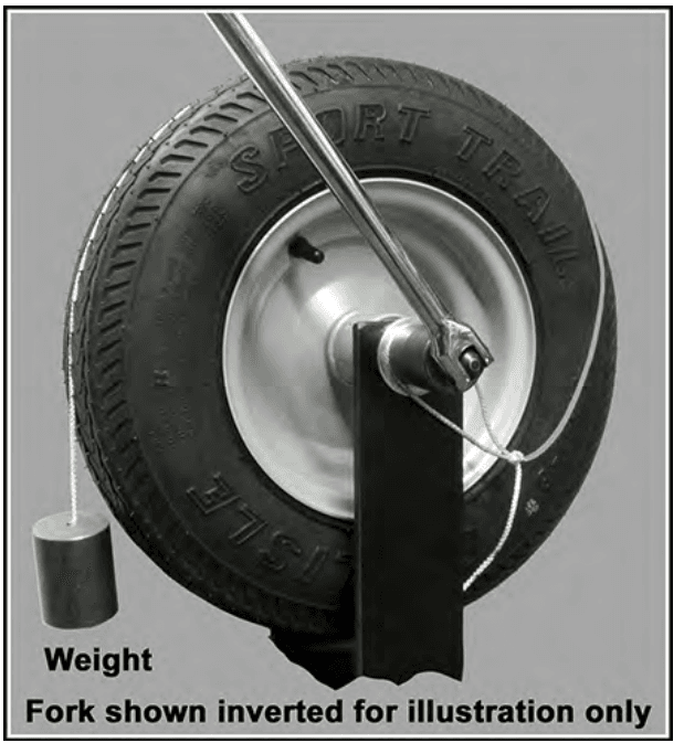
ADJUST FRONT WHEEL BEARINGS
The bearings must be lubricated before performing this procedure.
- Raise the front wheel(s) off of the ground and support with jack stands.
- While rotating the wheel, tighten the front axle nut until the wheel is difficult to rotate.
- Continue to rotate the wheel for 5 complete revolutions.
- Attach a rope to the tire and wrap it around the tire with 1 foot remaining hanging in the air.
- Tie a weight (see table and illustration below) to the end of the rope.

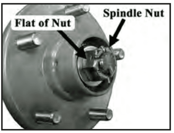
- Slowly loosen the axle nut until the hanging weight rotates the wheel then rotate to the nearest flat and install a new cotter pin.
- Remove the rope and weight.
- Spin the wheel and listen for any grinding noise. Any grinding noise may be an indication of worn
or damaged wheel bearings.
Note: Refer to the Replace Front Wheel Bearings section for information regarding the replacement of the wheel bearings. - Lower the vehicle.
- Reconnect the main positive and negative cables at the batteries.
- Remove the blocks from behind the wheels.
- Release the park brake and test drive the vehicle.
Tire Size Weight NEW (pounds / kg) Weight USED (pounds / kg) 4.80 x 8 2.15 / 0.975 1.00 / 0.454 5.70 x 8 1.99 / 0.902 0.93 / 0.422 4.00 x 8 2.15 / 0.975 1.01 / 0.485 500 x 8 1.99 / 0.902 0.93 / 0.422 8.50 x 8 2.02 / 0.916 0.94 / 0.426 8 x 2.50 4.23 / 1.919 1.97 / 0.894 10 x 3.5 3.38 / 1.533 1.56 / 0.708
FRONT WHEEL ALIGNMENT
Center the Steering
- Raise the front of the vehicle and support it with jack stands.
- Turn the front wheels so that they are in the straight-ahead position and then tie off the wheels so that they cannot turn from the straight-ahead position.
- Disconnect the drag link from the pitman’s arm. Refer to Replace the Ball Joints in the Steering section for information regarding removing the ball joint or rod end from the drag link.
- Center the steering gear and tie off the steering wheel so that it cannot rotate. Refer to the Center the Steering Gear section for information regarding the centering of the steering gear.
- At this point, both the steering wheel and the front wheels should be tied up and held in position. If one or the other is not tied up then you must start from the beginning.
- Loosen the ball joint clamps or the rod end jam nuts on the drag link.
Note: Remember the position and orientation of the clamps. - Adjust the drag link so that it can be easily inserted into the pitman’s arm.
- Tighten the ball joint or rod end nut as specified in the hardware torque table at the end of this section:
- If equipped with ball joints, position the ball joint clamps in their original location and orientation.
- Tighten the ball joint clamps as specified in the hardware torque table at the end of this section:
- Untie the steering wheel and the front wheels.
- Rotate the steering wheel from a full left turn to a full right turn and make sure that the ball joint clamps do not contact any other component.
Front-wheel alignment
Center the steering before aligning the front wheels.
- Turn the front wheels so that they are in the straight-ahead position and tie off the steering wheel so that it
cannot rotate. - Using a piece of chalk, mark a line around the center of both front tires.
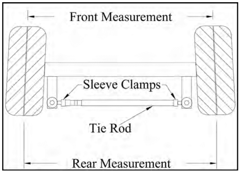
- Loosen the ball joint clamps or the rod end jam nuts on the tie rod.
Note: Remember the position and orientation of the ball joint clamps. - Lower the front wheels to the ground and push the vehicle back and forth a few feet to settle the suspension.

- Measure the distance between the chalk lines at the front of the tires.
- Measure the distance between the chalk lines at the rear of the tires.
- Adjust the tie rod so that the distance at the front and rear of the tires is within the toe in specification listed in the specification table at the end of this section.
- If equipped with ball joints, position the ball joint clamps in their original location and orientation.
- Tighten the ball joint clamps or the rod end jam nuts.
- Untie the steering wheel.
- Reconnect the main positive and negative cables at the batteries.
- Remove the blocks from behind the wheels.
- Release the parking brake and test drive.
REPLACE KING PIN/BUSHINGS
There are different types of king pin bushings depending on the configuration of your vehicle. This is a generic procedure that covers all three types of bushings. Refer to the illustration below for the type of bushing in your vehicle.
- Bronze bushings in the axle beam.
- Bronze bushings in the steering knuckle.
- Metal-backed Teflon bushings in the axle beam or suspension arm.
Note: Bronze bushings must be reamed or broached to the proper diameter after they are pressed into the axle beam or steering knuckle.
Note: It is recommended that the thrust washers or bearings should be replaced whenever replacing the kingpin bushings or kingpins. Refer to the Replacement Parts section for the orientation of the bearing or washers in your vehicle.
- Raise the front of the vehicle and support it with jack stands.
- Remove the steering knuckle. Refer to Replace the Steering Knuckle for information regarding removing the steering knuckle.
- Press the kingpin bushings out from the axle, steering knuckle, or suspension arm.
- Press new bushings into the axle, steering knuckle, or suspension arm. If equipped with bronze bushings, ream or broach the bushings per the specification listed at the end of this chapter.
- Inspect the kingpin for damage or wear. If any damage or wear is noted then the kingpin must be replaced.
- Reassemble in reverse order.
Note: Refer to Replace the Steering Knuckle for information on installing the steering knuckle. - Grease the bushings (bronze only).
- Lower the vehicle.
- Reconnect the batteries.
- Remove the blocks from behind the wheels.
- Release the park brake and test drive.

Drive Axle
CHECK OIL LEVEL
Fluid type and capacities are listed in the Lubrication chapter.
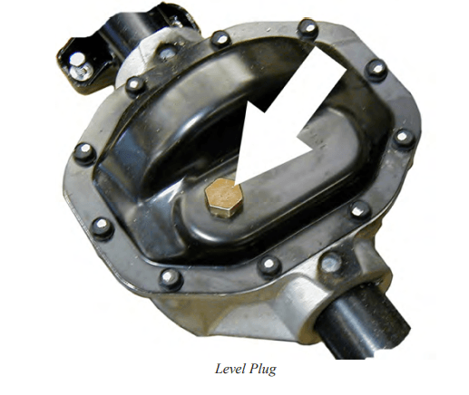
- Raise the drive wheels off of the ground and place a drain pan that can hold a minimum of 2-quarts of oil under the transmission level plug.
- Remove the level plug and lower the drive axle to the ground over the drain pan.
- A small amount of oil may come out. This indicates that the transmission has the correct amount of oil.
- If no oil comes out, then it may need to have oil added; add oil through the open-level plug until it
is overflowing out of the hole. - Reconnect the main positive and negative cables at the batteries, remove blocks from behind the
wheels and test drive the vehicle.
CHANGE OIL
section in the General Maintenance chapter.
- Raise the rear of the vehicle and support it with jack stands.
- Place a drain pan that can hold a minimum of 2-quarts of oil under the transmission.
- Remove the transmission cover plate to drain the oil.
- Reinstall the cover plate and remove the level plug.
- Add 1 pint (500 ml) of oil through the open-level plug.
- Lower to the ground over the drain pan and allow the excess to drain.
- Reinstall the plug.
- Reconnect the main positive and negative cables at the batteries, remove blocks from behind the wheels and test drive the vehicle.
DRIVE MOTOR
Remove
Note: In some vehicle configurations the transmission assembly will have to be removed to allow clearance to remove the motor. Refer to the Transmission section for information on removing the transmission assembly from the vehicle.
- Remove the motor wires from the motor.
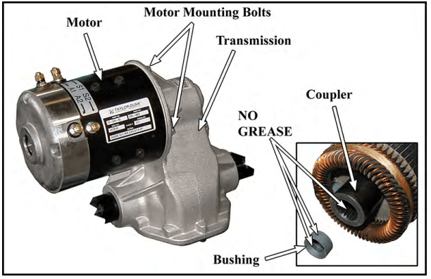
- Remove the bolts holding the motor to the transmission housing (see illustration).
- Slide the motor off of the transmission input shaft.
Install
- Remove the rubber bushing from the inside of the motor armature coupler (see illustration).
- Thoroughly clean all grease from the transmission input shaft, rubber bushing, and the motor armature coupling.
- Install the rubber bushing back into the motor armature coupling.
- Lightly grease the transmission input shaft only (see caution).
- Install the motor in reverse order.
- Tighten the motor mounting bolts per torque listed in the Hardware Torque table at the end of this section.
- Tighten the motor terminals per torque listed in the Hardware Torque table at the end of this section.
DIFFERENTIAL CASE
Disassemble
- Remove the transmission from the vehicle. Refer to the Transmission-Remove section for information on removing the transmission.
- Thoroughly clean the transmission assembly before disassembly.
- Remove the left and right axles from the transmission assembly. Refer to the Rear Axle section for information on removing the axles.
- Suspend the differential case over a drain pan that can hold a minimum of 2 quarts of oil.

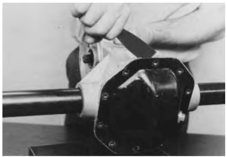
- Remove the differential case cover being careful not to bend or damage the case cover flange or
the sealing surface of the differential case.
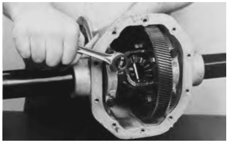
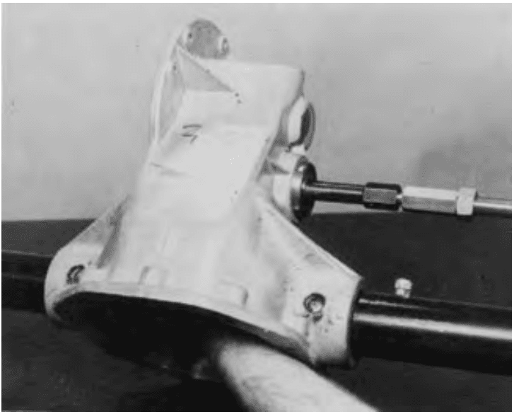
- Remove the differential bearing caps and remove the differential assembly from the housing.
Note: The bearing caps are marked for identification. When the transmission is reassembled they must be installed in their original position.
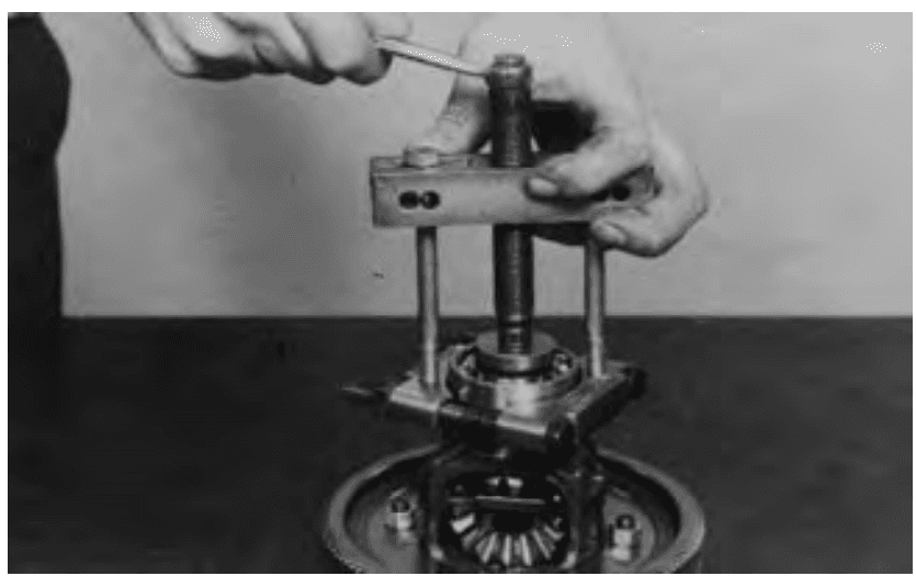
- Remove both bearings from the differential case.

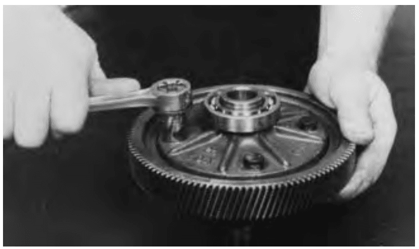
- Remove the final drive gear from the differential housing.

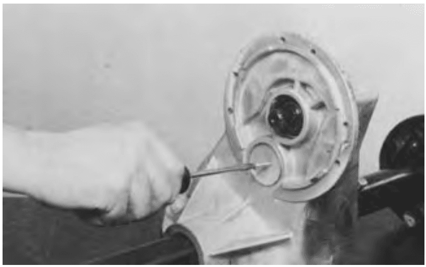
- Punch or drill a small hole into the center of both of the intermediate shaft bore plugs.
- Thread a sheet metal screw into each plug until the bore plug is forced out.

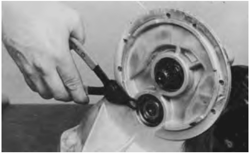
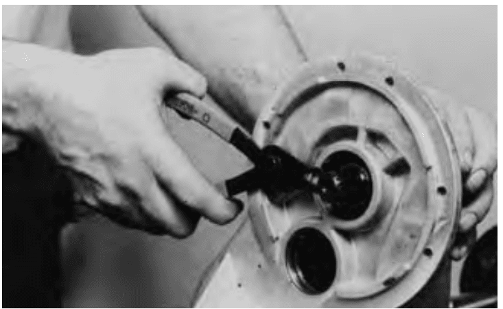
- Remove both snap rings from the intermediate shaft bore.

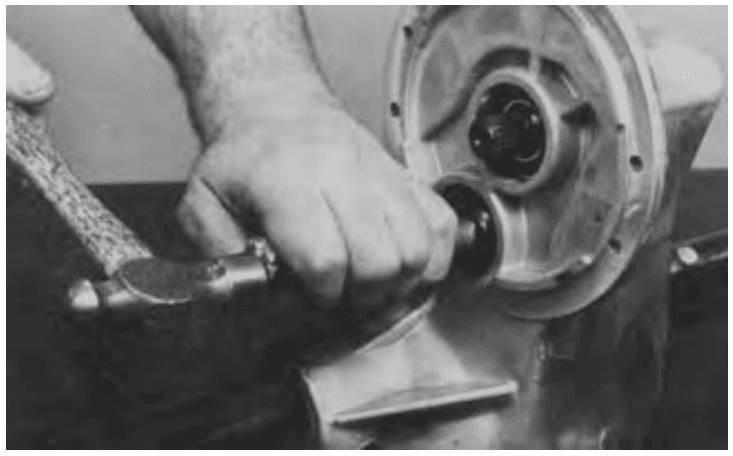
- Using a soft metal or hardwood dowel, drive the intermediate shaft through the bearing just enough to allow clearance for an ID bearing puller. Do not attempt to drive the shaft out of the
opposite end of the transmission.
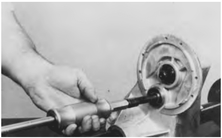
- Remove the intermediate bearing with an ID bearing puller.

- While supporting the shaft and gear assembly, repeat steps #12 and #13 for the opposite side
bearing and remove the intermediate shaft from the housing.
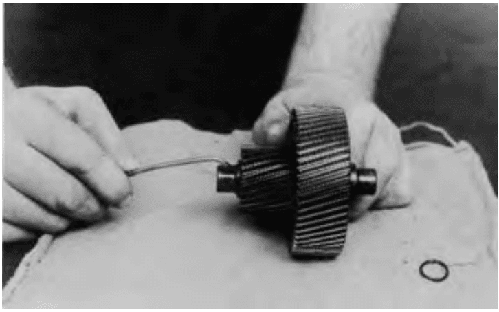
- Remove the o-rings from each end of the intermediate shaft.

- Remove the circlip from the input shaft.
- Remove the input shaft from the housing.
- Press the bearings off of the input shaft.

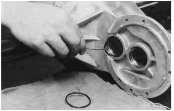
- Remove the o-rings from both sides of the intermediate shaft bore and the input shaft bore and discard the o-rings.
For more manuals by Taylor-Dunn, visit ManualsLibraryy
Taylor-Dunn B0-150-00 LoadMaster Electric Golf Cart-FAQs
How can I increase the speed of my Taylor-Dunn golf cart?
The throttle pedal controls the cart’s speed. Pressing it down increases speed, while releasing it slows the vehicle. Upgrading the motor or controller can also enhance speed.
Where can I find the serial number on my Taylor-Dunn cart?
The serial number is located on the data plate of the vehicle. The top two fields on the plate indicate the model and serial number.
What does error code F04012 mean?
Error code F04012 indicates a controller fault. Updating the software may resolve the issue, but if the problem persists, replacing the controller may be necessary.
How do I check the serial number of my cart?
The serial number is typically printed on a label on the side or back of the vehicle, often listed after “SN,” “S/N,” or “Serial Number.”
What is an SRO fault on the Taylor-Dunn cart?
An SRO (Start-up Sequence Out of Order) fault occurs when operator switches are not engaged in the correct sequence during startup.
Why does my Taylor-Dunn scale display an error message?
Common error causes include unstable placement, exceeding weight capacity, or improper sensor contact. Ensure the scale is on a flat surface and used correctly.
What does an error code indicate?
An error code is a numeric message that signals a system issue or operational fault. Checking the manual can help diagnose specific error codes.
How do I set a speed limit on my golf cart?
Speed limits are typically determined by the controller settings. Adjusting the controller or modifying the software can help regulate the cart’s top speed.
How can I increase torque on my electric golf cart?
Upgrading to a higher-power motor or adjusting the controller settings can improve torque and overall performance.

