Trane BAS-SVX36C Standard and Programmable Thermostats Installation
Introduction
This document provides installation, operation, and troubleshooting information for three Trane models of push-button thermostats:
- TheTrane Programmable 3-Heat/2-CoolThermostat:
- Trane PLM # X13511537-01
- Trane Clarksville part # BAYSTAT150A
- Service parts #THT02774
- TheTrane (non-programmable) 3-Heat/2-CoolThermostat:
- Trane PLM # X13511536-01
- Trane Clarksville part # BAYSTAT155A
- Service parts #THT02773
- TheTrane (non-programmable) 1-Heat/1-CoolThermostat:
- Trane PLM # X13511535-01
- Trane Clarksville part # BAYSTAT151A
- Service parts #THT02772
- Note: To identify the thermostat type, locate the Trane PLM # and the Trane PLM #/Trane Clarksville # on the thermostat circuit board.
Dimensions
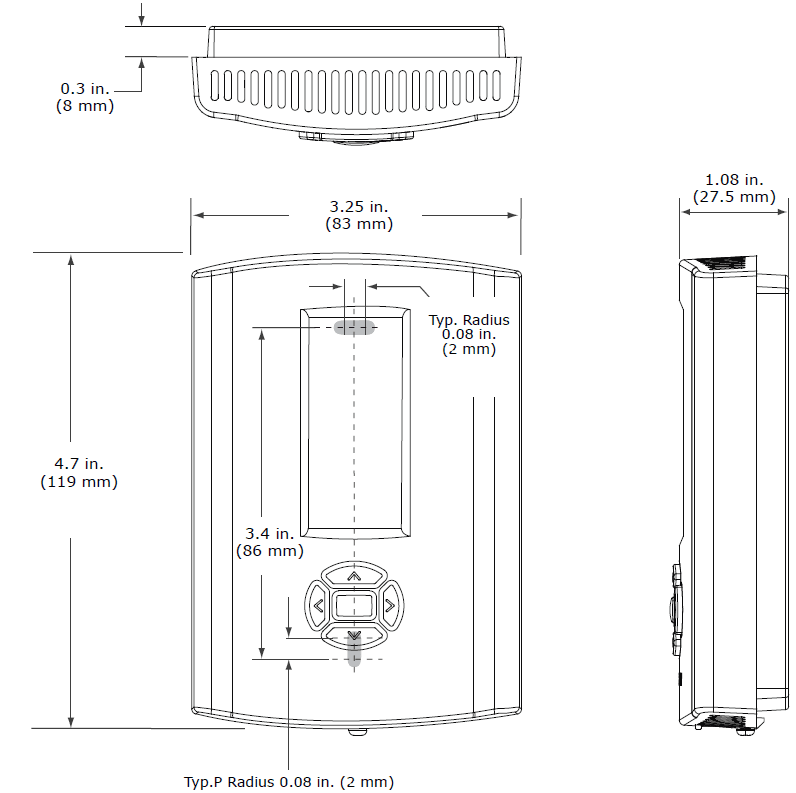
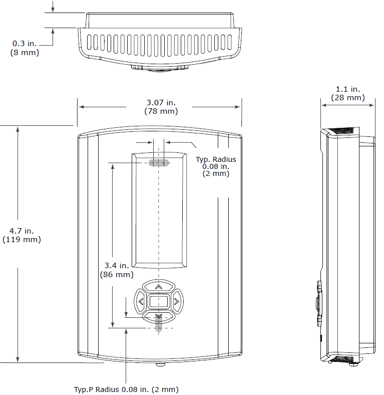
- Figure 1 and Figure 2 provide dimensions for each type of thermostat. The two non-programmable thermostats have the same dimensions; the programmable thermostat has slightly different dimensions.
- Figure 1. ProgrammableThermostat Dimensions

- Note: Drawing not to scale. Dimensions within ± 0.02 in. (± 0.5 mm)
- Figure 2. 1-Heat/1-Cool or 3-Heat/2-Cool (non-programmable)Thermostat Dimensions

Pre-Installation
This section provides the following pre-installation information:
- Location considerations
- Height requirements
- Mounting surfaces
- Maximum wire length
Location Considerations
When selecting a location, avoid the following:
- Areas of direct sunlight
- Areas in the direct airstream of air diffusers
- Exterior walls and other walls that have a temperature differential between the two sides
- Areas that are close to heat sources such as sunlight, appliances, concealed pipes, chimneys, or other heat-generating equipment
- Drafty areas
- Dead spots behind doors, projection screens, or corners
- Walls that are subject to high-vibration
- Areas with high humidity
- High-traffic areas (to reduce accidental damage or tampering)
Maximum Wire Lengths
Thermostat to HVAC Equipment
- The thermostat may not function properly if the total resistance of any of the thermostats to HVAC equipment wires exceeds 2.5 ohms. To ensure that wire length does not cause excess resistance, refer to Table 1 and ensure that the wires from the thermostat to the HVAC equipment are not too long.
- Table 1. MaximumThermostat to HVAC Equipment Wire Lengths
Copper wire size Maximum recommended wire length 22 AWG (0.33 mm2) 150 ft (46 m) 20 AWG (0.50 mm2) 240 ft (73 m) 18 AWG (0.75 mm2) 385 ft (117 m) - Remote Sensor to ProgrammableThermostat
- Because remote temperature sensors measure resistance, very long cable runs can cause slight errors in the measurement. For the highest temperature reading accuracy, avoid exceeding the maximum recommended wire lengths shown in Table 2.
- Table 2. Maximum Recommended Remote Sensor Wire Length
Copper wire size
Maximum recommended remote sensor wire length 22 AWG (0.33 mm2) 1000 ft (300 m) 20 AWG (0.50 mm2) 1500 ft (450 m) 18 AWG (0.75 mm2) 2500 ft (750 m) - Note: For 22 AWG (0.33 mm2) copper wires, the rate of error can be up to 0.5 °F (0.3 °C) per 100 OHM, which typically requires wire lengths in excess of 5000 ft (1500 m)
Installation
This section provides installation instructions. Before you begin, read through the pre-installation information, beginning on p. 9, and also verify the following conditions are met:
- A wire access hole is available at the thermostat location.
- The wires are accessible through the hole.
- The wires are attached to the appropriate terminals on the HVAC equipment.
- There is continuity (and not more than 2.5 ohms resistance) between the thermostat location and the HVAC equipment.
- The wires are accurately labeled or identified by color
General Practice
To wire the thermostat:
- Connect the wires to the terminal block(s) packaged in the box with the thermostat. (The programmable thermostat has two terminal blocks, the non-programmable thermostats have only one):
- Remove approximately 1/4 inch (6 mm) of insulation from the wires.
- Use the terminal block screws to securely fasten each wire into the terminal block.
- Refer to the section, “Terminal Identification,” p. 13, and the wiring diagrams on the pages that follow to determine the correct terminal for each wire.
- Note: In some case,s the terminal labels (Y, G, R, etc.) correctly correspond to the first letter of the color wire to which they are connected. However, you must verify which equipment terminals are connected at the other ends of the wires before connecting the wires to the thermostat.
- Align the pins on the circuit board with the holes on the bottom of the terminal blocks and gently push the wired terminal blocks into place on the circuit board. See Figure 5.
- Figure 5. Attaching the wired terminal blocks to the pins on the circuit board

- Figure 5. Attaching the wired terminal blocks to the pins on the circuit board
Wiring Diagrams
- The following diagrams show all of the common wiring scenarios you are likely to encounter.
1-Heat/1-CoolThermostat
- Use Table 3 and the diagrams that follow to correctly wire the thermostat for your system type.
- Table 3. SystemType Options for 1H/1C Non-ProgrammableThermostats
System Type Value for Option 01 See Diagram 1-heat/1-cool, conventional 0 Figure 6 1-heat/1-cool, heat pump without auxiliary heat 1 Figure 7 1-heat only, conventional without fan 2 Figure 8 1-heat only, conventional with fan 3 Figure 9 1-cool, Conventional 4 Figure 10
Configuration
Adverse Control System Behavior
Improper configuration could cause unwanted, possibly adverse control system behavior. Be sure to configure the thermostat according to your system type. To change the installation configuration:
- Apply electrical power to the thermostat.
- See the appropriate table for your thermostat type to determine the configuration options you need:
- Table 6, p. 27 for 3-Heat/2-Cool programmable thermostats
- Table 7, p. 31 for 3-Heat/2-Cool non-programmable thermostats
- Table 8, p. 32 for 1-Heat/1-Cool, non-programmable thermostats
- Write down your selections or other notes on the table.
- Enter installer configuration mode:
Live Electrical Components
- The circuit board is energized. Have a qualified licensed electrician or other individual who has been properly trained in handling live electrical components perform this step. Failure to follow all electrical safety precautions when exposed to live electrical components could result in death or serious injury.
- a. Remove the thermostat cover.
- b. Press and hold the configuration button for at least 3 sec
Table 6. Installation Options for 3-Heat/2-Cool programmable thermostat
| No. | Name | Default | Opts. | Descriptions |
| 0100 | Temperature | 0 | 0 | °F, 1-degree resolution |
| indication/ resolution | 1 2 | °F, 0.5 degree resolution °C, 1 degree resolution | ||
| 3 | °C with 0.5 degree resolution | |||
| 4 | °C with 0.1 degree resolution | |||
| 0110 | Clock format | 12 | 12 | 12 hour clock |
| 24 | 24-hour clock | |||
| 0120 | Year | 09 | 09-99 | 2009 – 2099 |
| 0121 | Month | 1 | 1-12 | Months of the year |
| 0122 | Day | 1 | 1-31 | Days of the month |
| 0125 | Daylight savings | 2 | 0 | Disabled |
| 1 | US (1987), changeover at 2:00 am | |||
| 2 | US (2007), changeover at 2:00 am | |||
| 3 | Europe, changeover at 1:00 am | |||
| 4 | Manual, changeover at 2:00 am | |||
| 0126 | Spring month(1) | 03 | 01-12 | The month in which the Spring daylight savings change occurs |
| 0127 | Spring day | 08 | 01-31 | The day on which the Spring daylight savings change occurs |
| 0128 | Fall month | 11 | 01-12 | The month in which the Fall daylight savings change occurs |
| 0129 | Fall day | 08 | 01-31 | The day on which the Fall daylight savings change occurs |
| 0130 | System selection | 8 | 1 | 1H/1C (conv) 1st Stage Heat (W), 1st Stage Comp (Y), Fan (G) |
| 2 | 1H/1C (HP) 1st Stage Comp (Y), Changeover (O/B), Fan (G) | |||
| 3 | 1H (Conv) 1st Stage Heat (W), without fan | |||
| 4 | 1H (Conv) 1st Stage Heat (W), Fan (G) | |||
| 5 | 1C (Conv) 1st Stage Comp (Y), Fan (G) | |||
| 6 | 2H/1C (HP) 1st Stage Comp (Y), Changeover (O/B), Auxiliary Heat (W1), Fan (G) | |||
| 7 | 2H/2C (Conv) 1st & 2nd Stage Heat (W,W2), 1st & 2nd Stage Comp (Y,Y2), Fan (G) | |||
| 8 | 2H/1C (Conv) 1st & 2nd Stage Heat (W,W2), 1st Stage Comp (Y), Fan (G) | |||
| 9 | 1H/2C (Conv) 1st Stage Heat (W), 1st & 2nd Stage Comp (Y,Y2), Fan (G) | |||
| 10 | 2H/2C (HP) 1st & 2nd Stage Comp (Y,Y2), Changeover (O/B), Fan (G) | |||
| 11 | 3H/2C (HP) 1st & 2nd Stage Comp (Y,Y2), Changeover (O/B), Auxiliary Heat (W1), Fan (G) |
Table 6. Installation Options for 3-Heat/2-Cool ProgrammableThermostat (continued)
| No. | Name | Default | Opts. | Descriptions |
| 0233 | Scheduling mode day options | 0 | 0 1
2 3 | 1 day – Mo-Su shares the same schedule 5+1+1 days – Mo-Fr share a schedule; Sa and Su each have an independent schedule 5+2 days – Mo-Fr share a schedule; Sa-Su share a schedule 7 days – Each day has an independent schedule |
| 0240 | Heat temperature range stops(6) | 90 | 40 – 90 4 – 32 | 40° F to 90° F 4° C to 32° C |
| 0241 | Cool temperature range stops(7) | 50 | 50 – 99 10 – 37 | 50° F to 99° F 4° C to 32° C |
| 0260 | Temperature display offset(8) | 0 | -3 -2 -1 0 1 2 3 | –3° F (–1.5° C) –2° F (–1.0° C) –1° F (–0.5° C) None 1° F (0.5° C) 2° F (1.0° C) 3° F (1.5° C) |
| 0270 | Extended fan-on time heat(9)(10) | 0 | 0 90 | Off 90 sec |
| 0271 | Extended fan-on time cool(9)(7) | 0 | 0 40 | Off 40 sec |
| 0300 | Restore factory defaults | 0 | 0 1 | No – do not restore Yes – reset all installer options to default except calendar, and system selection – options 0120-0122 and 0125-0130 do not reset. |
Table 7. Installation Options for 3-Heat/2-Cool Non-programmable thermostat
| No. | Name | Default | Opts. | Descriptions |
| 01 | System type | 0 | 0
1
2 3 4 5
6 7 8
9 | 1H/1C, conventional – 1st stage heat (W), 1st stage compressor (Y) 1H/1C, heat pump without auxiliary heat – 1st stage compressor (Y), changeover (O/B) 1H, conventional without fan – 1st stage heat (W) 1H, conventional with fan – 1st stage heat (W), fan (G) 1C, conventional – 1st stage compressor (Y) 2H/1C, heat pump with auxiliary heat – 1st stage compressor (Y), changeover (O/B), auxiliary heat (Aux/E) 2H/1C, conventional – 1st & 2nd stage heat (W,W2), 1st stage compressor (Y) 1H/2C, conventional – 1st stage heat (W), 1st & 2nd stage compressor (Y, Y2) 2H/2C, heat pump without auxiliary heat – 1st & 2nd stage compressor (Y, Y2), changeover (O/B) 3H/2C, heat pump with auxiliary heat – 1st & 2nd stage compressor (Y, Y2), changeover (O/B), auxiliary heat (Aux/E) |
| 02 | Changeover valve | 0 | 0 1 | O/B terminal energized in cooling O/B terminal energized in heating |
| 03 | Fan control(1) | 0 | 0 1 | Gas or oil furnace, equipment controls fan for heating Electric furnace, thermostat controls fan in heating |
| 04 | Stage 1 heat cycle rate(2) | 5 | 1-10 | Cycles per hour for 1st stage conventional heat – only available on systems with conventional heat |
| 05 | Stage 1 compressor cycle rate(2) | 3 | 1-5 | Cycles per hour for 1st stage compressor – only available on systems with cool stages |
| 06 | Manual/Auto changeover | 0 | 0
1
2 | Manual changeover (heat/cool/off) – manually changeover between heat, cool, and off Auto changeover (heat/cool/auto/off) – manually change between heat, cool, and off, or select automatic changeover Auto changeover only (auto) – no manual changeover |
| 07 | Temperature indication/ resolution | 0 | 0 1 2 3 4 | °F with 1-degree resolution °F with 0.5 degree resolution °C with 1-degree resolution °C with 0.5 degree resolution °C with 0.1 degree resolution |
| 08 | Compressor protection | 5 | 0-5 | Minutes for compressor off time – only available on heat pump systems or systems with cool stages – (Minutes specified here are added to the 5-minute base off time.) |
| 09 | Heat temperature range stop | 90 | 40-90 | Heating high-temperature range stops at °F. (4.5-32°C) |
| 10 | Cool temperature range stop | 50 | 50-99 | Cooling low-temperature range stop in °F. (10-37°C) |
| 11 | Power supply frequency | 0 | 0 1 | 60 Hz 50 Hz |
| 12 | Deadband(3) | 3 | 2 3 4 5 6 7 8 9 | 2°F (1.0°C) 3°F (1.5°C) 4°F (2.0°C) 5°F (2.5°C) 6°F (3.0°C) 7°F (3.5°C) 8°F (4.0°C) 9°F (4.5°C) |
| 13 | Stage 2 heat cycle rate(2) | 9 | 1-10 | Cycles per hour for 2nd stage conventional heat – only available for conventional systems with at least two stages of conventional heat |
| 14 | Auxiliary heat cycle rate(2) | 5 | 1-10 | Cycles per hour for auxiliary heat – only for heat pump systems with more heat than cool stages |
| 15 | Emergency heat cycle rate(2) | 5 | 1-10 | Cycles per hour for emergency heat – only for heat pump systems with more heat than cool stages. |
| 16 | Stage 2 compressor cycle rate(2) | 3 | 1-5 | Cycles per hour for 2nd stage compressor – only for systems with two cool stages |
| 17 | Auxiliary heat control | 0 | 0 1 | Comfort Economy |
| 18 | Restore factory defaults | 0 | 0 1 | No – do not reset Yes – reset all installation configurations (all settings in this table) to default settings, except System selection |
Operation
- This section provides general descriptive and procedural information intended for typical daily operators of the thermostat.
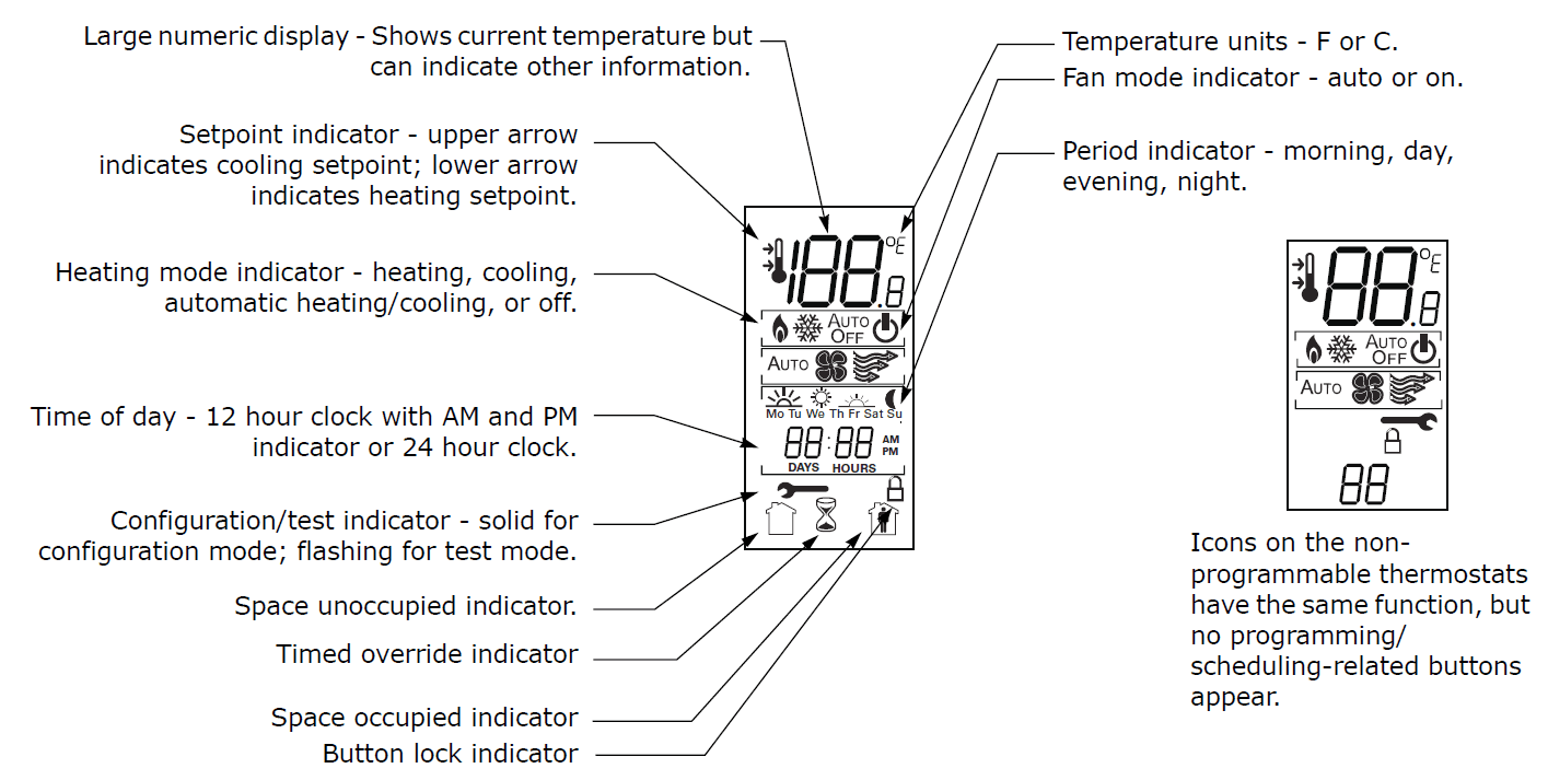
- Icon Descriptions
- Figure 36 describes the icons visible on the front of the thermostat.
- Note: Except when the thermostat is powering up, when all of the icons are shown for 2 sec, only some of the icons will be visible at once.
- Figure 36. Thermostat Icons

Operational and Programming Reference Information
- This section provides additional information that may be useful for understanding thermostat operation or programming.
Deadband
- The thermostat automatically maintains a temperature deadband between the heating setpoint and the cooling setpoint whenever automatic changeover (heat-to-cool or cool-to-heat mode) is enabled. The temperature range of the deadband is 2–9 °F (1.0–4.5°C) and is specified in the installation configuration options (see “Configuration,” p. 26). If you attempt to change a temperature setpoint to within the deadband of its opposing setpoint, the opposing setpoint will automatically be pushed to the next value that satisfies the deadband. (See Figure 38.)
- Heat and Cool Cycling Rate
- The heat and cool cycling rate, expressed in cycles per hour (CPH) indicates how often the heating or cooling system is turned on when the temperature is within the temperature differential from the setpoint, which is 1°F (0.5°C). There are ten options (1–10) for heat stages and five options (1–5) for cool stages. The number selected is the maximum number of times the stage is cycled in 1 hr. For example, when the system is set to 5 CPH, it runs at 12 min cycles with variable duty cycles.
- Depending on the heating or cooling load, which is measured by feedback from the sensor thermistor and/or temperature error, the system could run at 50% duty cycle (6 min ON and 6 min OFF), 80% duty cycle (9.6 min ON and 2.4 min OFF), or other variations of the duty cycle.
- Note: The cycling rate described above is only active when the temperature is within the temperature differential. If the temperature is outside of the temperature, the heating and cooling equipment will either be fully on or fully off accordingly. (See Figure 38.)
- Figure 38. General Heat and Cool Cycling Rate Diagram

Error Codes
| Code | Description |
| E0 | Thermistor Error; occurs when the configured thermistor reading is out of range (less than 14°F (-9.9°C) or greater than 122°F (50°C). If this error occurs: • All Heat/Cool outputs turn off. • If the fan mode is Auto, the thermostat turns off the fan. • If the fan mode is On, the thermostat leaves the fan on. |
| E3 | Permanent data error. Access error or checksum error is detected. |
| E4 | Input voltage out of range – too low or too high. Input voltage is lower than 18Vac or higher than 34Vac. The error code display will remain on for 30 sec after the detection of out-of-range input voltage. |
| E5 | RTC Error (this error can only appear on the programmable thermostat). |
| E7 | Memory error (write and read 0x55 and 0xAA failed). Only checked during the power-up test. |
Troubleshooting Table
| Problem | Solution |
| Error code E0 – Thermistor error. | • For non-programmable thermostats and programmable thermostats set to use internal temperature sensor (configuration options #210 set to 0, 1, or 2): The thermistor is defective or the local temperature is out of range. Replace or repair the thermostat through a qualified Trane supplier. • For programmable thermostats with configuration option #210 set to 3: Check the sensor terminals S1 and S2 for secure connection. If wires are securely connected, try replacing the sensor. |
| Error code E4 – Input voltage out of range | • Check the input voltage to the thermostat. It must be within the range of 18Vac to 32 Vac rms. |
| Error codes E3, E5, or E7 | • Cycle the power to the thermostat. • If it does not recover to normal operation, have it serviced or replaced by a qualified Trane supplier. |
| Blank display | • Check the power supply. • If the power supply is ok, have the thermostat serviced or replaced by a qualified Trane supplier. |
| Erratic display appearance or contrast | • Check the power supply. • Check the frequency configuration (Configuration option #210 for the programmable thermostat or #11 for non-programmable thermostats) to make sure that you are using the correct frequency setting for your power supply. • If the power supply and frequency setting are ok, have the thermostat serviced or replaced by a qualified Trane supplier. |
| Buttons do not respond | • Make sure the thermostat modes are not locked. See “Locking or Unlocking Modes,” p. 40. • Cycle the power to the thermostat. • If the modes are not locked and cycling the power do not solve the problem, have the thermostat serviced or replaced by a qualified Trane supplier. |
| “–F” or “–C” flashes | • Temperature is outside of the measurable range. The temperature reading should be correct when the temperature is within the measurable range. |
| Fan settings are not visible | • Check the system status. If the status is Off, the fan settings will not appear. • Check the configuration options to verify that the fan is enabled: For programmable thermostats, check options 0130 and 0151; For non-programmable thermostats, check options 01 and 03. |
Thermostat Specifications
| Programmable Thermostat | Non-Programmable Thermostats | |
| Input power | 24Vac, 50Hz or 60Hz (18Vac to 32Vac) (Power supply frequency selected using installation configuration option #190) | 24Vac, 50Hz or 60Hz (18Vac to 32Vac) (Power supply frequency selected using installation configuration option #11) |
| Wire size | 18 to 22 AWG | 18 to 22 AWG |
| Output terminal ratings | 1A @ 30Vac | 1A@ 30Vac |
| Indoor temperature display range | +15 to +122°F (–9.5 to +50°C) | +32 to +99°F (0 to +37°C) |
| Outdoor (remote) temperature display range | –31 to +122°F (–35 to +50°C) | NA |
| Storage temperature | –40 to +158°F (–40 to +70°C) | –40 to +158°F (–40 to +70°C) |
| Accuracy | ±1.4°F (±0.8°C) over a range of 50 to 90 °F (10 to 32.2°C) | ±1.4°F (±0.8°C) over a range of 50 to 90 °F (10 to 32.2°C) |
| Resolution | Configurable: 1.0°F, 0.5°F, 1°C, 0.5°C, 0.1°C | Configurable: 1.0°F, 0.5°F, 1°C, 0.5°C, 0.1°C |
| Power consumption | < 1VA | < 1VA |
| Housing materials and rating information | Polycarbonate/ABS blend, UV protected, UL 94-5VA flammability rating, suitable for application in a plenum. | Polycarbonate/ABS blend, UV protected, UL 94- 5VA flammability rating, suitable for application in a plenum. |
| Mounting | 3.24 in (8.26 cm) for two mounting screws (supplied) | 3.24 in (8.26 cm) for two mounting screws (supplied) |
For more manuals by Trane visit, ManualsLibraryy
Trane BAS-SVX36C Standard and Programmable Thermostats Installation-FAQs
How do I access the installer settings on my Trane thermostat?
Press the Menu button, then press and hold Next for about 5 seconds until “Service” appears. Press Select until you see “Installer Settings,” then press Select again to enter the menu.
How does a Trane thermostat work?
Trane thermostats use temperature sensors to detect indoor conditions and automatically switch between heating and cooling to maintain your desired comfort level.
What does the Auto setting do on a Trane thermostat?
When set to Auto, the thermostat will activate heating or cooling as needed to maintain the selected temperature.
How do I upgrade my thermostat to a digital model?
To replace an analog thermostat with a digital one, turn off power, remove the old faceplate, label and detach the wires, install the new thermostat, reconnect the wires, and attach the new faceplate.
Why is my Trane thermostat in Recovery Mode?
Recovery Mode means the thermostat is adjusting from an energy-saving mode to reach the desired temperature at the scheduled time. Some models may display “Smart Recovery” or have an indicator light.
How does a thermostat function?
Mechanical thermostats regulate temperature using metallic strips that expand with heat, completing or breaking a circuit to turn heating on or off.
How do I unlock the screen on my Trane thermostat?
Press and hold the plus (+) and minus (-) buttons simultaneously for 3-4 seconds to unlock the screen.
How do I control my thermostat settings?
Use the up/down buttons or dial to adjust the temperature. For programmable models, enter the programming mode and follow the manufacturer’s instructions to set temperature schedules.
How does the thermostat timer work?
The thermostat monitors room temperature and communicates with the boiler timer to switch on heating when the temperature drops below the set range, maintaining consistent comfort.


