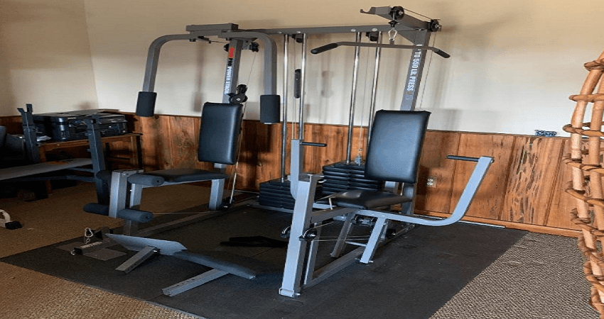
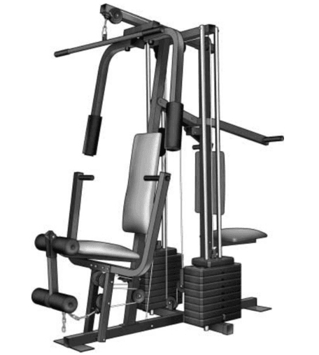
Weider Pro 9645 Home Gym
BEFORE YOU BEGIN
- Thank you for selecting the versatile WELDER PRO® 6900 weight system. The weight system offers a selection of weight stations designed to develop every major muscle group of the body. Whether your goal is to tone your body, build dramatic muscle size and
strength, or improve your cardiovascular system, the weight system will help you to achieve the specific results you want. - For your benefit, read this manual carefully before using the weight system. If you have questions after reading this manual, please see the front cover of this manual. To help us assist you, note the product model number and serial number before contacting us. The model number and the location of the serial number decal are shown on the front cover of this manual.
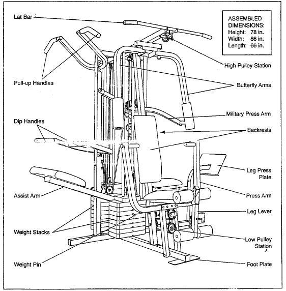
- Before reading further, please review the drawing below and familiarize yourself with the parts that are labeled.
ASSEMBLY
To make assembly easier, carefully read the following information and instructions:
- Assembly requires two persons.
- Because of its weight and size, assemble the weight system in the location where it will be used. Make sure that there is enough clearance to walk around the weight system.
- Place all parts in a cleared area and remove the packing materials. Do not dispose of the packing materials until assembly is completed.
- For help identifying small parts, use the PART IDENTIFICATION CHART on page 5
- The following tools (not included) may be required for assembly:
- two adjustable wrenches

- one rubber mallet

- one standard screwdriver

- one Phillips screwdriver

- two adjustable wrenches
- Assembly may be more convenient if you have a socket set, a set of open-end or closed-end wrenches, or a set of ratchet wrenches.
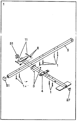
- Before beginning assembly, be sure that you have read and understand the Information in the box above. Locate and open the parts bag labeled “FRAME ASSEMBLY.” Press two 2″ Square Outer Caps (51) onto Cap (27) into the Base (4). Insert six 5/16″ x 2 1/2″ Carriage Bolts (1) up through the Stabilizer (5). Insert two 5/16″ x 2 1/2″ Carriage Bolts up through the Base (4).Attach the Base (4) to the Stabilizer (5) with two 5/16″ x 2 3/4″ Bolts (11), two 5/16″ Flat Washers (8), and two 5/16″ Nylon Locknuts (3). Do not tighten the Nylon Locknuts yet.

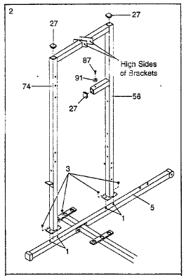
- Slide the Assist Upright (74) and the Leg Press Upright (56) onto the indicated 5/16″ x 2 1/2″ Carriage Bolts (1) in the Stabilizer (5). The high side of the brackets on the Assist Upright and Leg Press Upright should be on the side shown. Hand-tighten four 5/16″ Nylon Locknuts (3) onto the Carriage 80Its. Do not tighten the Nylon Locknuts yet.Press two 2″ Square Inner Caps (27) into the Leg Press Upright (56). Press a 2 Square Inner Cap into the Assist Upright (74). Attach the Rubber Bumper (91) to the Leg Press Upright (56) with the #8 x 1/2 Self-tapping Screw (87).

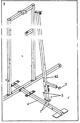
- Slide the Front Upright (42) onto the 5/16″ x 2 1/2″ Cardage Bolts (1) in the Base (4). Hand-tighten a 5/16″ Nylon Locknut (3) onto each Carriage Bolt. Do not tighten the Nylon Locknuts yet.

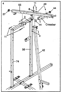
- .Press a 2″ Square Inner Cap (27) into the end of the Top Frame (55). Press a 13/4″ Square Inner Cap (44) into each end of the crossbar on the Top Frame. Press two 1″ Round Inner Caps (49) into the top of the crossbar. Attach the Top Frame (55) to the Assist Updght (74) and the Leg Press Upright (56) with two 5/16″ x 2 3/4″ Bolts (11) and two 5/16″ Nylon Lock, nuts (3).Attach the Top Frame (55) to the Front Updght (42) with two 5/16″ x 2 3/4″ Bolts (11), two 5/16″ Flat Washers (8), and two 5/16″ Nylon Locknuts (3).

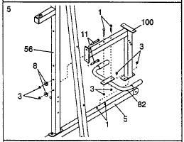
- Press a 2″ Square Inner Cap (27) into the end of the Top Frame (55). Press a 13/4″ Square Inner Cap (44) into each end of the crossbar on the Top Frame. Press two 1″ Round Inner Caps (49) into the top of the crossbar. Attach the Top Frame (55) to the Assist Updght (74) and the Leg Press Upright (56) with two 5/16″ x 2 3/4″ Bolts (11) and two 5/16″ Nylon Lock, nuts (3).Attach the Top Frame (55) to the Front Updght (42) with two 5/16″ x 2 3/4″ Bolts (11), two 5/16″ Flat Washers (8), and two 5/16″ Nylon Locknuts (3). Slide the Rear Seat Frame (100) onto the indicated 5/16″ x 21/2″ Carriage Bolts (1) in the Stabilizer (5). Hand-tighten two 5/16″ Nylon Locknuts (3) onto the Carriage Bolts. Do not tighten the Nylon Locknuts yet.Attach the other end of the Rear Seat Frame (100) to the Leg Press Upright (56) with two 5/16″ x 23/4″ Bolts (11), two 5/16″ Flat Washers (8), and two 5/16″ Nylon Locknuts (3). Attach the Handle (82) to the Rear Seat The frame (100) with two 5/16″ x 21/2″ Carriage Botts (1) and two 5/16″ Nylon Locknuts (3). Tighten all Nylon Locknuts used in steps 1-5.

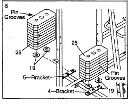
- Set two Weight Bumpers (19) on the bracket on the Base (4) as shown. Set two Weight Bumpers (19) on the bracket on the Stabilizer (5). Stack ten Weights (25) onto the bracket on the Stabilizer (5). Stack eight Weights onto the bracket on the Base (4). Be sure that the pin grooves are all on the same side of each stack of Weights. Be careful not to tip either stack of Weights (25) until step 8 is complete.

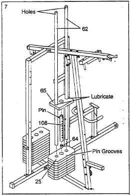
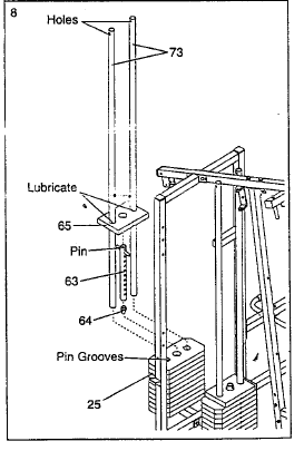
- Press a Weight Tube Bumper (64) into the end of the Short Weight Tube (I08). Insert the Weight Tube into the front stack of Weights !25). Be sure that the pin on the Weight Tube is sitting in the pin grooves in the top Weight. Lubricate the inside of the holes in a Top Weight (65). Set the Top Weight onto the front stack of Weights (25), and Insert both Long Weight Guides (62) into the stack of Weights. Be sure that the holes In the Weight Guides are at the top, as shown.

- Press a Weight Tube Bumper (64) into the end of the Long Weight tube (63). Insert the Weight Tube into the rear stack of Weights (25). Be sure that the pin on the Weight The tube is sitting in the pin grooves in the top Weight.Lubricate the inside of the holes in the other Top Weight (65). Set the Top weight onto the rear stack of weights (25). Insert both Short Weight Guides (73) into the stack of Weights. Be sure that the holes in the Weight Guides are at the top, as shown.

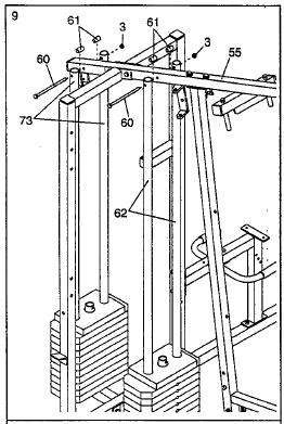
- Attach the upper ends of the Short Weight Guides (73) to the Top Frame (55) with a 5/16″ x 6″ Bolt (60), two 1/2″ x 3/4″ Spacers (61), and a 5/16″ Nylon Locknut (3). Attach the upper ends of the Long Weight Guides (62) to the Top Frame (55) in the same manner.

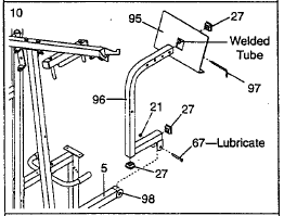
- Locate and open the parts labeled “ARM ASSEMBLY.” Be sure there is a Bushing (98) on each side of the Stabilizer (5). Press a 2″ Square Inner Cap (27) into each end of the Leg Press Arm (96). Lubricate a 3/8″ x 3 1/4″ Bolt (67). Attach the Leg Press Ann (96) to the Stabilizer (5) with the Bolt and a 3/8″ Nylon Locknut (21). Do not overtighten the Nylon LocknuL The Leg Press Arm must be able to pivot freely. Align the welded tubes on the Leg Press Plate (95) with one set of holes in the Leg Press Arm (96). Attach the Leg Press Plate to the Leg Press Arm with the Press Pin (97).

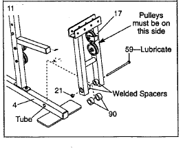
- Press a 1″ x 7/8″ Plastic Bushing (90) onto each welded spacer on the Press Frame (17). Slide the Press Frame into place onto the Base (4). Note: This will be a tight fit. The Plastic Bushings should fit on each end of the Indicated tube in the Base. Make sure that the pulleys are on the side shown. Lubricate the 3/8″ x 8″ Bolt (59). Attach the Press Frame (17) to the Base (4) with the Bolt and a 3/8″ Nylon Locknut (21).

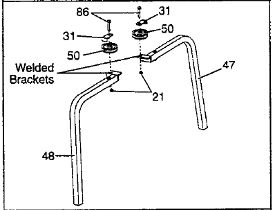
- Identify the Right Arm (48) and the Left Arm (47). Note the position of the welded bracket on each Arm. Arm identification is essential for step 14. Attach a “V”-Pulley (50) and a Long Cable Trap (31) to the Right Arm (48) with a 3/8″ x 2 1/2′ Bolt (86) and a 3/8″ Nylon Locknut (21). Do not tighten the Nylon Locknut yet. Attach a.”V”-Pulley (50) and a Long Cable Trap (31) to the Left Arm (47) in the same manner.

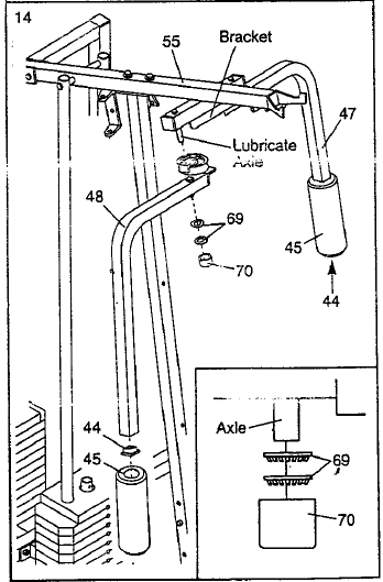
- Lubricant both axles on the Top Frame (55). Slide the Right Arm (48) onto the right axle. Attach the Left Arm (47) in the same manner. Press 1 3/4″ Square Inner Caps (44) into the lower ends of the Right and Left Arms (47, 48). Wet the lower end of each Arm with soapy water. Slide a 1(7 Pad (45) onto the lower end of each Arm.

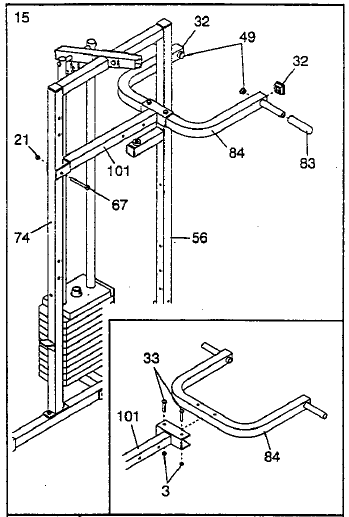
- See the inset drawing. Attach the Military Press Arm (84) to the Pivot Arm (101) with two 5/16″ x 2 1/4″ Bolts (33) and two 5/16″ Nylon Locknuts (3). Press two 1 1/2″ Square Inner Caps (32) into the Military Press Arm (84). Press two 1″Round Inner Caps (49) into the Military Press Arm. Slide two 5″ Plastic Handgdps (83) onto the Military Press Arm. Attach the Pivot Arm (101) to the Assist Upright (74) with a 3/8″ x 3 1/4″ Bott (67) and a 3/8″ Nylon Locknut (21).

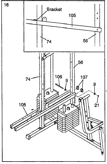
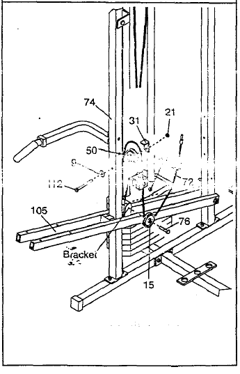
- Press two 1″ x 2″ Inner Caps (107) into the Assist Arm (105). Attach the Assist Arm (105) to the Leg Press Upright (56) with a 3/8″ x 6″ Bolt (106), two 3/8″ Flat Washers (9), and a 3/8″ Nylon Locknut (21). See the inset drawing, The Assist Arm must be attached to the lowest hole In the Leg Press Upright (58). The Assist Arm must also be below the welded bracket on the Assist Upright (74).

- Wrap the Military Press Cable (72) around a “V”-Putley (50). Attach the _/”-Pulley and a Long Cable Trap (31) to the Assist Upright (74) with a 3/8″ x 4 112″ Bolt (112), a 3/8″ Flat Washer (9), and a 3/8″ Nylon Locknut (21). Be sure that the Long Cable Trap is turned to hold the Cable in place and that the cable is routed around the Pulley as shown, Wrap the Military Press Cable (72) around a 3 1/2″ Pulley (15).Attach the Pulley to the other bracket on the Assist Arm (105) with a 3/8″ x 1 3/4″ Bolt (76) and a 3/8″ Nylon Locknut (21). Be sure that the Cable Is between the Pulley and the Assist Arm and that the Cable and Pulley move smoothly.

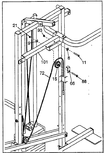
- Slide a 5/16″ Flat Washer (8) onto a 5116″ x 2 3/4″ Bolt (11). Insert the Bolt through the indicated hole in the Pivot Arm (101). The Bolt must be inserted from the side shown. Fully tighten a 5/16″ Nylon Jam Nut (93) onto the Boil Wrap the Military Press Cable (72) around a 3 1/2″ Pulley (15). Attach the Pulley and a Cable Trap (66) to the Pivot Arm (101) with the 3/8″ x 3 3/4″ Bolt (88), a 3/8″ Flat Washer (9), and a 3/8″ Nylon Locknut (21). Be sure that the Pulley is on the side shown and that the Cable Trap is positioned to hold the Cable in place.

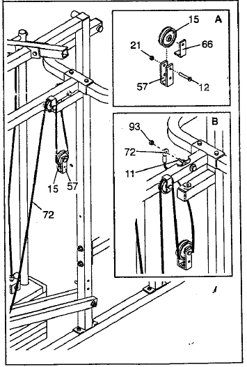
- See the inset drawing A. Attach a 3 1/2″ Pulley (15) and a Cable Trap (66) to the upper hole in a Long “U”-Bracket (57) with a 318″ x 2″ Bolt (12) and a 3/8″ Nylon Locknut (21). Ensure the Cable Trap is inside the Long “U”-Bracket. (Note: This may come preassembled.) Route the Military Press Cable (72) through the Long “U”-Bracket (57) and the 3 1/2″ Pulley (15). Be sure that the Cable Is In the groove of the Pulley and that the Cable
and Pulley moves smoothly.See the inset drawing B, Slide the end of the Military Press Cable (72) onto the end of the 5/16″ x 2 3/4 Bolt (11). Thread another 5/16″ Nylon Jam Nut (93) onto the Bolt. Do not fully tighten the second Jam Nut. There must be room between the two Jam Nuts for the end of the Cable to pivot.
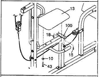
- Attach one end of a Seat (13) to the Rear Seat Frame (100) with two 1/4″ x 1/2″ Screws (18). Attach the other end of the Seat to the Rear Seat Frame with a 1/4″ Flat Washer (10) and a 1/4″ x 2 1/2″ Screw (43).

- Attach the Assist Seat (104) and the Angle Bracket (110) to the Assist Arm (105) with four 1/4″ Flat Washers (10) and four 1/4″ x 2 1/2″ Screws (43).

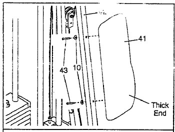
- Attach the Front Backrest (41) to the Front Upright (42) with two 1/4″ x 2 1/2″ Screws (43) and two 1/4″ Flat Washers (10). The Backrest must be oriented as shown.

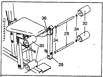
- Press two 3/4″ Round Inner Caps (34) into each Pad Tube (28). Insert a Pad Tube (28) into the Front Seat Frame (36). Slide a Foam Pad (30) onto each end of the Pad Tube. Insert the other Pad Tube (28) into the Leg Lever (29). Slide a Foam Foam Pad (30) onto each end of the Pad Tube.

WEIGHT RESISTANCE CHART
This chart shows the approximate weight resistance at each weight station. “Top” refers to the 5.5 lb. weight. The other numbers refer to the 12.5 lb. weight plates. The butterfly and resistance listed are the resistance for the butterfly arm.
For more manuals by Weider visit, ManualsLibraryy
Weider Pro 9645 Home Gym-FAQs
What exercises can I perform on the Weider Pro 9645?
The Weider Pro 9645 offers a variety of exercises, including chest presses, lat pulldowns, leg curls, arm curls, and more for a full-body workout.
How much weight does the Weider Pro 9645 support?
The gym includes a weight stack system with up to 210 lbs of resistance, making it suitable for beginner to intermediate users.
Can multiple users work out on the Weider Pro 9645 simultaneously?
Yes, the Weider Pro 9645 is designed for up to three users to work out at the same time, thanks to its multi-station setup.
How do I maintain the Weider Pro 9645 Home Gym?
Regularly check cables for wear, lubricate moving parts as instructed in the manual, and ensure all bolts are tightened securely.
Is assembly required for the Weider Pro 9645?
Yes, the gym requires assembly. The manual provides step-by-step instructions to help you set it up correctly.
What space is needed for the Weider Pro 9645 Home Gym?
Allow a workout area of approximately 7 feet by 6 feet to ensure safe and comfortable use of the machine.
Does the Weider Pro 9645 include a warranty?
Warranty terms vary by retailer. Check your purchase details or the user manual for specific coverage information.
Can I adjust the resistance levels on the Weider Pro 9645?
Yes, you can adjust resistance by selecting different weight plates on the stack to match your fitness level and exercise.
Is the Weider Pro 9645 suitable for beginners?
Absolutely! The versatile design and adjustable resistance make it ideal for beginners and seasoned athletes alike.
Where can I find replacement parts for the Weider Pro 9645?
Replacement parts can be ordered from the manufacturer’s website or authorized service centers listed in the manual.

