Yamaha Grizzly 660 Bike

MACHINE IDENTIFICATION
GENERAL INFORMATION
VEHICLE IDENTIFICATION NUMBER
The vehicle identification number 1 is stamped into the left side of the frame.

MODEL LABEL
The model label 1 is affixed to the frame. This information will be needed to order spare parts.

FEATURES
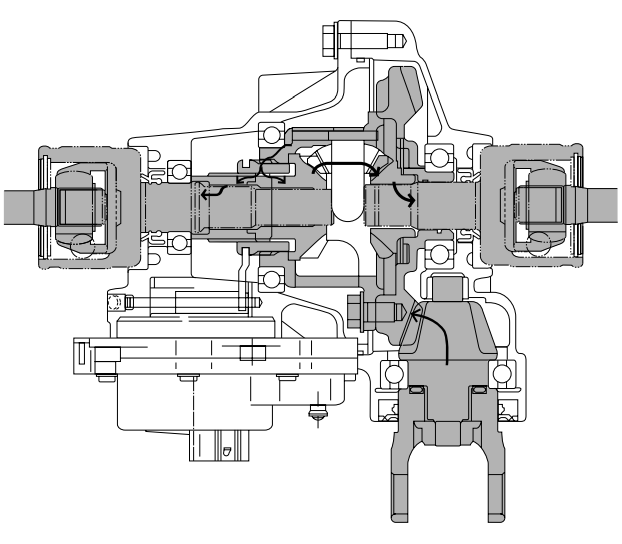
FRONT DIFFERENTIAL
- Adapter
- Drive clutch
- Differential side gear (left)
- Differential pinion gear
- Ring gear
- Differential side gear (right)
- Drive pinion gear
- Gear motor
- A. To the front wheel
- B. From the middle gear

2WD
Power is transmitted as follows: middle gear → front drive shaft → drive pinion gear 7 → ring gear 5 → differential pinion gear 4. In the 2WD mode, the left differential side gear 3 and the drive clutch 2 are not engaged, therefore, the left side gear runs idle and does not transmit power to the left front constant velocity joint.

4WD
When the 4WD mode is selected, the gear motor is operated, and the drive clutch 2 moves to the right and engages with the left differential side gear 3. Accordingly, power is transmitted as follows: ring gear 5 → differential pinion gear 4 → left differential side gear 3 → drive clutch 2 → adapter 1 → left front constant velocity joint.
Meanwhile, power from the differential pinion gear 4 is transmitted to the right front constant velocity joint via the right differential side gear 6.
The ring gear 5 and the drive clutch 2 are not engaged at this time. Therefore, the rotational difference that occurs between the right and left wheels, while the handlebar is being turned, is absorbed by the difference in the rotational speeds of the ring gear 5 and the left differential side gear 3.

4WD (Diff-Lock)
When the 4WD (Diff-Lock) mode is selected, the gear motor moves the drive clutch 2 further to the right, which causes the ring gear 5 and the drive clutch 2 to engage. As a result, power is transmitted directly from the ring gear 5 to the drive clutch 2, then to the left front constant velocity joint via the adapter 1.
Meanwhile, because the ring gear 5 and the drive clutch 2 are engaged, the ring gear 5, the drive clutch 2, and the right differential side gear 6 become locked coaxially. Thus, power is transmitted as follows: differential pinion gear 4 → right differential pinion gear 6 → right front constant velocity joint.
When the ATV is in the 4WD (Diff-Lock) mode, the right and left wheels rotate constantly at the same speed, which affects the maneuverability of the ATV (e.g., making it difficult to steer). Therefore, the maximum traveling speed is limited to 35 km/h (22 mph).
In addition, the 4WD (Diff-Lock) mode can be engaged only when the ATV is stopped. Even if an attempt is made to select this mode when the ATV is traveling, it will only result in a standby condition (i.e., when the differential lock select switch and the differential gear are not matched).
- When the ATV is traveling
Even if the 4WD (Diff-Lock) mode is selected, the gear motor will stand by, instead of operating. Therefore, the ATV can be driven in the normal 4WD mode. When this occurs, the differential gear lock indicator light in the speedometer unit will flash to alert the driver that the control is on standby. When the ATV is stopped, the control transfers to the condition described in (2).
 - When the ATV is stopped
The gear motor operates to connect the drive clutch to the differential case, thus resulting in the differential lock condition. When this occurs, the differential gear lock indicator light in the speedometer unit changes to a constant illumination.
* Until the drive clutch and the differential case mesh together (i.e., the splines are unmeshed), the engine misfires to control the engine speed. During this time, the differential gear lock indicator light in the speedometer unit continues to flash.

Shift mechanism
A new shift mechanism with a parking position has been added to the YFM660F.
- Shift cam
- Shift fork guide bar
- Drive axle
- Stopper lever shaft
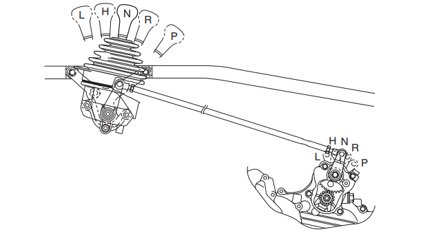

Parking
- L (Low), H (High), N (Neutral), and R (Reverse) positions
The end of the stopper lever is held by the return spring 1. Then, the stopper lever tab is separated from the drive axle stopper to free the drive axle. - P (Park) position
When the drive select lever is shifted to the “P” position, the cam lever of the shift cam pushes up on the end of the stopper lever. Then, the stopper lever tab pushes against the drive axle stopper to lock the drive axle. - Not synchronized
If the stopper lever tab and the drive axle stopper are not synchronized, the torsion spring is compressed. As a result, the spring pushes the stopper lever tab against the drive axle stopper and waits until the synchronization is completed. When the stop lever tab and the drive axle are synchronized, the stop lever tab pushes against the drive axle stopper to lock the drive axle.
- Stopper lever
- Return spring
- Shift cam
- Drive axle

TRANSMISSION
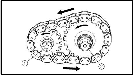
To create a compact, 3-axle transmission, a chain drive has been adopted for the reverse transmission.
- Secondary shaft
- Drive axle
- Middle drive shaft
- Low wheel gear
- Chain

- Secondary shaft
- Drive axle
L (Low) or H (High) mode
When the transmission is in either the low or high mode, the drive axle is driven via the secondary shaft and gear. Therefore, the rotation of the drive axle is the opposite of the secondary shaft.

R (Reverse) mode
When the transmission is in the reverse mode, the drive axle is driven via the drive chain. Therefore, the rotation of the drive axle is the same as the secondary shaft. (As a result, the rotation of the drive axle is opposite to that of the low and high modes.)
 IMPORTANT INFORMATION
PREPARATION FOR REMOVAL PROCEDURES
- Remove all dirt, mud, dust, and foreign material before removal and disassembly.
- Use proper tools and cleaning equipment. Refer to the “SPECIAL TOOLS” section.
- When disassembling the machine, always keep mated parts together. This includes gears, cylinders, pistons, and other parts that have been “mated” through normal wear. Mated parts must always be reused or replaced as an assembly.
- During machine disassembly, clean all parts and place them in trays in the order of disassembly. This will speed up assembly and allow for the correct installation of all parts.
- Keep all parts away from any source of fire.
REPLACEMENT PARTS
- Use only genuine Yamaha parts for all replacements. Use oil and grease recommended by Yamaha for all lubrication jobs. Other brands may be similar in function and appearance, but inferior in quality.
GASKETS, OIL SEALS, AND O-RINGS
- Replace all gasketssealssal, and O-rings when overhauling the engine. All gasket surfaces, oil seal lips, and O-rings must be cleaned.
- Properly oil all mating parts and bearings during reassembly. Apply grease to the oil seal lips.
LOCK WASHERS/PLATES AND COTTER PINS
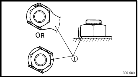
- Replace all lock washers/plates 1 and cotter pins after removal. Bend lock tabs along the bolt or nut flats after the bolt or nut has been tightened to specification.
BEARINGS AND OIL SEALS
- Install bearings and oil seals so that the manufacturer’s marks or numbers are visible. When installing oil seals, apply a light coating of lightweight lithium base grease to the seal lips. Oil bearings liberally when installing, if appropriate.
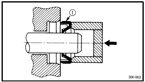
- Oil seal
CAUTION:
Do not use compressed air to spin the bearings dry. This will damage the bearing surfaces.

- Bearing
CIRCLIPS
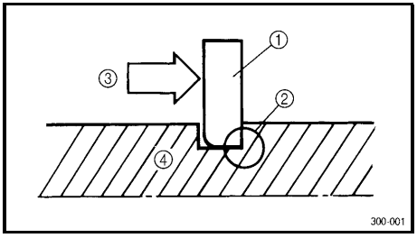
- Check all circlips carefully before reassembly. Always replace piston pin clips after one use. Replace distorted circlips. When installing a circlip 1, make sure that the sharp-edged corner 2 is positioned opposite the thrust 3 it receives. See sectional view. 4 Shaft
CHECKING OF CONNECTIONS
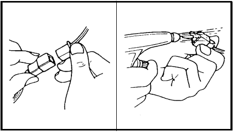
Check the connectors for stains, rust, moisture, etc.
- Disconnect:
- Connector

- Connector
- Check:
- UConnector
Moisture → Dry each terminal with an air blower.
Stains/rust → Connect and disconnect the terminals several times.
- UConnector
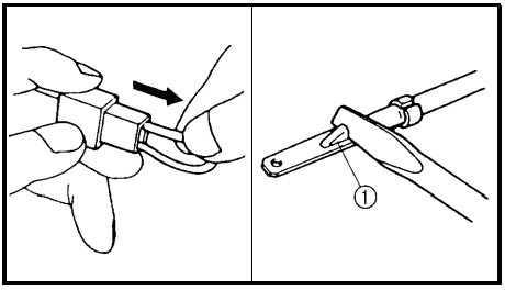
- Check:
- Connector leads
Looseness → Bend up the pin 1 and connect the terminals.
- Connector leads
- Connect:
- Connector terminals
NOTE:
The two terminals “click” together.
- Connector terminals
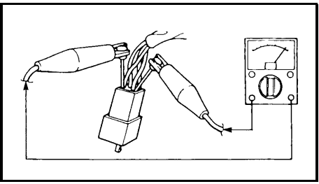
- Check:
- Continuity (using a pocket tester)

NOTE: - If there is no continuity, clean the terminals.
- When checking the wire harness, be sure to perform steps 1 to 3.
- As a quick remedy, use a contact revitalizer available at most drug stores.
- Check the connector with a pocket tester as shown.
- Continuity (using a pocket tester)
SPECIFICATIONS
GENERAL SPECIFICATIONS
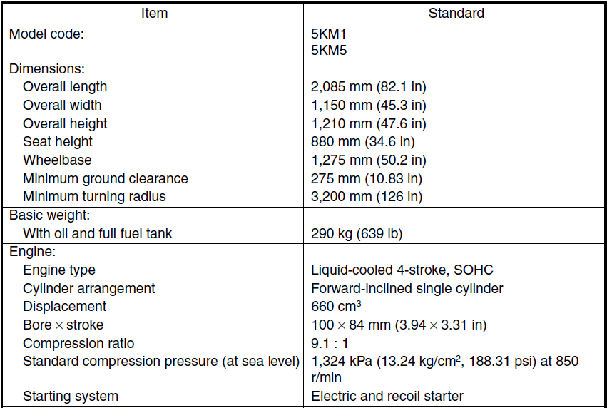
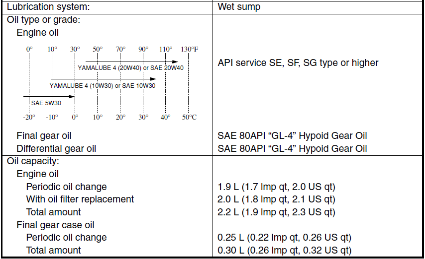
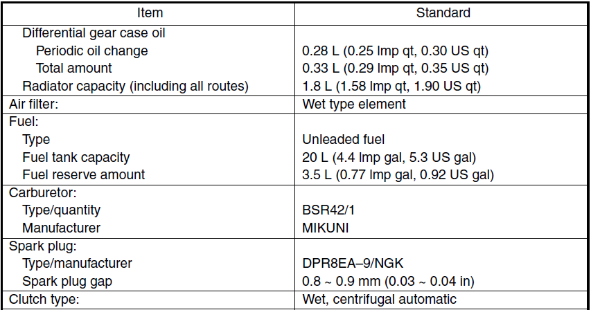
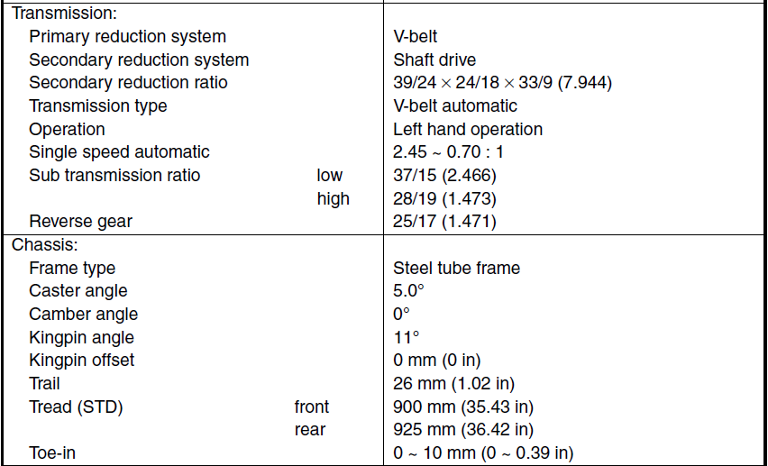

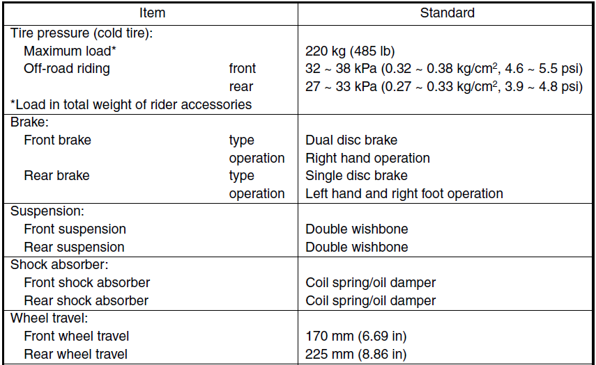
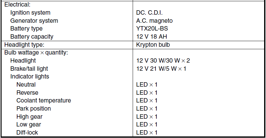
TROUBLESHOOTING
DRIVE TRAIN
TROUBLESHOOTING
The following conditions may indicate damaged shaft drive components:
Symptoms
- A pronounced hesitation or “jerky” movement during acceleration, deceleration, or sustained speed. (This must not be confused with engine surging or transmission characteristics.)
- A “rolling rumble” noticeable at low speed; a high-pitched whine; a “clunk” from a shaft drive component or area.
- A locked-up condition of the shaft drive train mechanism, no power transmitted from the engine to the front and/or rear wheel.
Possible Causes
- Bearing damage.
- Improper gear lash.
- Gear tooth damage.
- Broken drive shaft.
- Broken gear teeth.
- Seizure due to lack of lubrication.
- Small foreign objects are lodged between the moving parts.
NOTE:
Areas A, B, and C above may be extremely difficult to diagnose. The symptoms are quite subtle and difficult to distinguish from normal machine operating noise. If there is reason to believe these components are damaged, remove the components and inspect them.
Inspection notes
Investigate any unusual noises.
The following “noises” may indicate a mechanical defect:
- A “rolling rumble” noise during coasting, acceleration, or deceleration. The noise increases with front and/or rear wheel speed, but it does not increase with higher engine or transmission speeds.
Diagnosis: Possible wheel bearing damage. - A “whining” noise that varies with acceleration and deceleration.
Diagnosis: Possible incorrect reassembly, too little gear lash.CAUTION: Too little gear lash is extremely destructive to the gear teeth. If a test ride following reassembly indicates this condition, stop riding immediately to minimize gear damage. - A slight “thunk” is evident at low-speed operation. This noise must be distinguished from normal machine operation.
Diagnosis: Possible broken gear teeth.
WARNING
Stop riding immediately if broken gear teeth are suspected. This condition could result in the shaft drive assembly locking up, causing loss of control of the machine and possible injury to the rider.
Inspect
- Drained oil
Drained oil shows large amounts of metal particles. → Check the bearing for seizure.
NOTE:
A small amount of metal particles in the oil is normal.
Inspect
- Oil leakage
Inspection steps:
- Clean the entire machine thoroughly, then dry it.
- Apply a leak-localizing compound or dry powder spray to the shaft drive.
- Road test the machine for the distance necessary to locate the leak.
Leakage → Inspect the component housing, gasket, and/or seal for damage.
Damage → Replace the component.
NOTE:
- An apparent oil leak on a new or nearly new machine may be the result of a rust-preventative coating or excessive seal lubrication.
- Always clean the machine and recheck the suspected location of an apparent leakage.
Troubleshooting chart
When basic conditions “a” and “b” exist, check the following points:
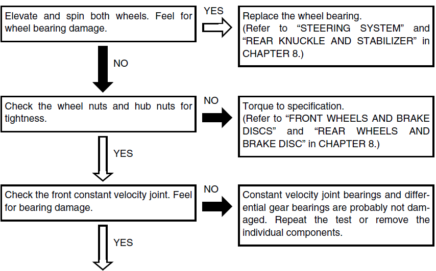
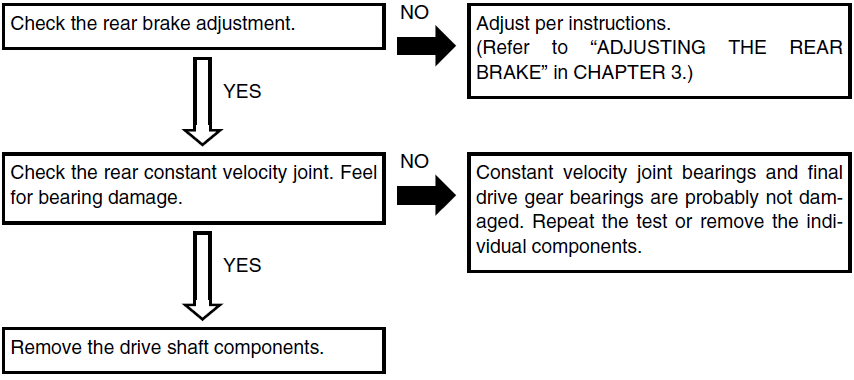
For more manuals by Yamaha, visit ManualsLibraryy
Yamaha Grizzly 660 Bike- FAQs
How much oil does a Yamaha Grizzly 660 take?
The Yamaha Grizzly 660 requires 2.11 quarts (2 liters) of 10W-40 engine oil for an oil change.
What type of oil should I use?
Use SAE 10W-40 (conventional or synthetic) designed for ATVs. Yamalube is recommended.
How do I check the oil level?
Run the engine for 3-5 minutes, then turn it off.
Wait 1-2 minutes, remove the dipstick, wipe it clean, and reinsert.
Check the level—it should be between the upper and lower marks.
What coolant does the Grizzly 660 use?
Use Yamacool Pre-Diluted Antifreeze Coolant or equivalent ethylene glycol ATV coolant.
What brake fluid should I use?
Only use DOT 3 or DOT 4 brake fluid (Yamalube recommended). Do not mix with DOT 5.
Is the Grizzly 660 fuel-injected?
Yes, the Grizzly 660 FI (2007+) has fuel injection, while older models (2002-2006) are carbureted.
How many cylinders does it have?
A single-cylinder, 660cc, 4-stroke engine.
Does it have a wet clutch?
Yes, it uses a wet clutch system (bathed in oil).
How often should I change the drive belt?
Every 1,500–2,000 miles or sooner if you notice slipping, jerking, or poor acceleration.
Does the Grizzly 660 have power steering?
No, EPS (Electric Power Steering) was introduced in later Grizzly 700 models.

 IMPORTANT INFORMATION