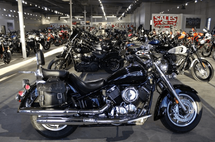
Yamaha V star 1100 Bike

WARNINGS, CAUTIONS, AND NOTES
The terms WARNING, CAUTION, and NOTE have specific meanings in this manual.
A WARNING emphasizes areas where injury or even death could result from negligence. Mechanical damage may also occur. WARNINGS should be taken seriously.
CAUTION emphasizes areas where equipment damage could result. Disregarding a CAUTION could cause permanent mechanical damage, though injury is unlikely.
A NOTE provides additional information to make a step or procedure easier or clearer. Disregarding a NOTE could cause inconvenience, but would not cause equipment damage or personal injury.
SAFETY
Professional mechanics can work for years and never sustain a serious injury or mishap. Follow these guidelines and practice common sense to safely service the motorcycle.
- Do not operate the vehicle in an enclosed area. The exhaust gases contain carbon monoxide, a poisonous gas that is odorless, colorless, and tasteless. Carbon monoxide levels build quickly in a small enclosed area, and it can cause unconsciousness and death in a short time. Make sure the work area is properly ventilated, or operate the vehicle outside.
- Never use gasoline or any extremely flammable liquid to clean parts. Refer to Cleaning Parts and Handling Gasoline Safely in this section.
- Never smoke or use a torch in the vicinity of flammable liquids, such as gasoline or cleaning solvent.
- When welding or brazing on the motorcycle, remove the fuel tank, carburetor, and shocks to a safe distance at least 50 ft. (15 m) away.
- Use the correct type and size tool to avoid damaging fasteners.
- Keep tools clean and in good condition. Replace or repair worn or damaged equipment.
- When loosening a tight fastener, be guided by what would happen if the tool slips.
- When replacing fasteners, make sure the new fasteners are of the same size and strength as the original ones.
- Keep the work area clean and organized.
- Wear eye protection anytime the safety of your eyes is in question. This includes procedures involving drilling, grinding, hammering, compressed air, and chemicals.
- Wear the correct clothing for the job. Tie up or cover long hair so it cannot be caught in moving equipment.
- Do not carry sharp tools in clothing pockets.
- Always have an approved fire extinguisher available. Make sure it is rated for gasoline (Class B) and electrical (Class C) fires.
- Do not use compressed air to clean clothes, the motorcycle, or the work area. Debris may be blown into your eyes or skin. Never direct compressed air at yourself or someone else. Do not allow children to use or play with any compressed air equipment.
- When using compressed air to dry rotating parts, hold the part so it can not rotate. Do not allow the force of the air to spin the part. The air jet is capable of rotating parts at extreme speeds. The part may be damaged or disintegrate, causing serious injury.
- Do not inhale the dust created by brake pad and clutch wear. In most cases, these particles contain asbestos. In addition, some types of insulating materials and gaskets may contain asbestos. Inhaling asbestos particles is hazardous to health.
- Never work on the vehicle while someone is working under it.
- When placing the vehicle on a stand, make sure it is secure before walking away.
Handling Gasoline Safely
Gasoline is a volatile, flammable liquid and is one of the most dangerous items in the shop. Because gasoline is used so often, many people forget that it is hazardous. Only use gasoline as fuel for gasoline internal combustion engines. When working on a vehicle, remember that gasoline is always present in the fuel tank, fuel lines, and carburetors. To avoid a disastrous accident when working
around the fuel system, observe the following precautions:
- Never use gasoline to clean parts. See Cleaning Parts in this section.
- When working on the fuel system, work outside or in a well-ventilated area.

- Do not add fuel to the fuel tank or service the fuel system while the vehicle is near open flames, around sparks, or near someone who is smoking. Gasoline vapor is heavier than air; it collects in low areas and is more easily ignited than liquid gasoline.
- Allow the engine to cool completely before working on any fuel system component.
- When draining the carburetor, catch the fuel in a plastic container and then pour it into an approved gasoline storage container.
- Do not store gasoline in glass containers. If the glass breaks, a serious explosion or fire may occur.
- Immediately wipe up spilled gasoline with rags. Store the rags in a metal container with a lid until they can be properly disposed of, or place them outside in a safe place for the fuel to evaporate.
- Do not pour water onto a gasoline fire. Water spreads the fire and makes it more difficult to extinguish. Use a class B, BC or ABC fire extinguisher to put out a gasoline fire.
- Always turn off the engine before refueling. Do not spill fuel onto the engine or exhaust system. Do not overfill the fuel tank. Leave an air space at the top of the tank to allow room for the fuel to expand due to temperature fluctuations.
GENERAL INFORMATION
SHOP SUPPLIES
Lubricants and Fluids
Periodic lubrication helps ensure a long service life for any type of equipment. Using the correct type of lubricant is as important as performing the lubrication service, although in an emergency, the wrong type of lubricant is better than none. The following section describes the types of lubricants most often required. Make sure to follow the manufacturer’s recommendations for lubricant types.
Engine oils
Generally, all liquid lubricants are called oil. They may be mineral-based (including petroleum-based), natural-based (vegetable and animal bases), synthetic-based, or emulsions (mixtures). Engine oil is classified by two standards: the American Petroleum Institute (API) service classification and the Society of Automotive Engineers (SAE) viscosity rating. This information is on the oil container label. Two letters indicate the API service classification (SF, SG, etc.). The number or sequence of numbers and letters (10W-40, for example) is the oil’s viscosity rating. The API service classification and the SAE viscosity index are not indications of oil quality.
The service classification indicates that the oil meets specific lubrication standards. The first letter in the classification (S) indicates that the oil is for gasoline engines. The second letter indicates the standard the oil satisfies.
Always use an oil with a classification recommended by the manufacturer. Using an oil with a different classification can cause engine damage.
Viscosity is an indication of the oil’s thickness. Thin oils have a lower number, while thick oils have a higher number. A W after the number indicates that the viscosity testing was done at low temperature to simulate cold-weather operation. Engine oils fall into the 5- to 50-weight range for single-grade oils.
Most manufacturers recommend multigrade oil. Multigrade oils (10W-40, for example) are less viscous (thinner) at low temperatures and more viscous (thicker) at high temperatures. This allows the oil to perform efficiently across a wide range of engine operating conditions. The lower the number, the better the engine will start in cold climates. Higher numbers are usually recommended when operating an engine in hot weather.
FRONT SUSPENSION AND STEERING
FRONT FORK
Before concluding that the front fork legs have major problems, drain the fork oil and refill the fork legs with the proper type and quantity of fork oil as described under Assembly in this section. If they are still having problems, such as poor damping, leaking around the seals, or a tendency to bottom or top out, follow the service procedures in this section. To simplify fork service and to prevent the mixing of parts, service each fork leg individually.
Removal (Fork Leg Will Not Be Serviced)
NOTE
The photographs show the front fork removal and installation for an XVS1100A model. Except for the fork covers, these photographs also apply to XVS1100 models.
- Securely support the motorcycle with a front-end stand.
- Remove the front wheel, along with the brake calipers and brake hose holders.
NOTE
Insert vinyl tubing or a piece of wood between the pads in the caliper. That way, if the brake lever is inadvertently squeezed, the pistons will not be forced out of the caliper. If this does happen, the caliper might have to be disassembled to reseat the pistons. By leg must be reinstalled to the same height during assembly.
HANDLEBAR
Removal/Installation
CAUTION
Cover the front fender, frame, and fuel tank with a heavy cloth or plastic tarp to protect them from accidental brake fluid spills. Immediately wash spilled brake fluid off any painted or plated surface. Brake fluid will destroy the finish. Use soapy water and rinse the area thoroughly.
NOTE
If the handlebar replacement is not required, proceed to Step 10.
- Securely support the motorcycle on level ground.
- Remove all cable ties that secure cables to the handlebars.
- Remove the two master cylinder clamp bolts and remove the master cylinder from the handlebars. Secure the master cylinder to the frame with a bungee cord. Make sure the master cylinder reservoir remains upright. This prevents brake fluid spills and helps keep air out of the brake system. Do not disconnect the hydraulic brake line.
- Remove the right handlebar switch assembly.
- Remove the handlebar weight and slide the throttle grip assembly from the handlebar.
- Remove the left handlebar switch.
- Slide the clutch lever boot away from the adjuster and loosen the clutch cable locknut. Rotate the adjuster to provide maximum slack in the cable and disconnect the cable end from the clutch hand lever.
- Disconnect the electrical lead from the clutch switch.
- Remove the clutch lever nuts and bolts, and remove the clutch lever assembly.
- Remove the caps, then loosen the clamp bolts on the upper handlebar holders.
- Remove the upper handlebar holders from the handlebar and lift the handlebar from the lower handlebar holders.
- If necessary, replace the left-hand grip as follows:
- Unscrew the handlebar end and remove it from the handlebar.
- Insert a thin-bladed screwdriver under the hand grip.
- Squirt electrical contact cleaner under the hand grip and twist it quickly to break its seal and remove it.
- Apply a thin layer of rubber cement to the end of the handlebar when installing a new grip.
- Check the hand grip after 10 minutes to make sure it is tight.
WARNING
Do not ride the motorcycle with a loose hand grip. Loss of control will occur.
REAR SUSPENSION AND FINAL DRIVE
SUSPENSION LINKAGE
Removal/Installation
The rear suspension linkage consists of a relay arm and two connecting arms.
- Remove the shock absorber as described in this chapter.
- On the left side, remove the nut and washer from the upper and lower connecting arm bolts.
- Remove each connecting arm bolt and lower the connecting arms from the motorcycle.
- Remove the nut from the relay arm bolt.
- Pull the relay arm bolt from the right side and lower the relay arm from the frame mount.
- Installation is the reverse of removal. Note the following:
- Lubricate the bearings, collars, and seals with molybdenum disulfide grease.
- Install the bolts from the right side and the nuts from the left.
- Torque the relay arm nut and the connecting arm nuts to 48 N•m (35 ft.-lb.).
Inspection
- Clean and dry the hardware, collars, and mounts.
- Inspect the connecting arms (Figure 7) for dents or other damage. Also, inspect the mounts for cracks or elongation.
- Inspect the needle bearings in the relay arm as follows:
NOTE
A different length collar is used in each mount in the relay arm. Install each collar in the proper mount.
- Remove the collar from the relay arm mount.
- Wipe excess grease from the bearing, and visually inspect the needles for pitting, wear, or other damage.
- Insert the collar into its bearing and turn the collar by hand. The bearing should turn smoothly without binding or excessive noise.
- If any bearing is worn or damaged, replace it as described in Needle Bearing Replacement in this section.
- Two bearings are used in the middle relay arm mount. If either bearing in this mount is worn, replace both bearings as a set. Install each bearing so it is flush with the outside edge of the bearing bore.
- When installing a needle bearing in a mount that uses just one bearing, center the bearing in the mount.
Needle Bearing Replacement
- Use a blind bearing remover to remove each bearing from the middle mount on the relay arm. Follow the instructions from the tool’s manufacturer.
- Use a hydraulic press to remove a needle bearing from the front and rear relay mounts. Support the relay arm in the press and use a driver that matches the diameter of the needle bearing.
- Thoroughly clean and dry the bearing bore.
- Pack the new bearing with molybdenum disulfide grease.
- Use a swing arm bearing installer, like the Motion Pro Swing Arm Bearing Tool, to install the new bearing. Follow the manufacturer’s instructions.
- If a tool is not available, one can be fabricated from a socket, three large washers, a threaded rod, and two nuts. Assemble the washers, threaded rod, bearing, and nuts. Hold the lower nut with a wrench and turn the upper nut to press the bearing into the bearing bore. Turn the nut slowly and watch the bearing carefully. Make sure it does not turn sideways.
- Position a bearing in its bore as described in Swing Arm or Suspension Linkage.
FINAL DRIVE ASSEMBLY
Removal/Installation
- Securely support the motorcycle on a level surface.
- If the final gearcase is to be serviced, drain the gearcase oil.
- Remove the rear wheel (Chapter Ten) and set it on wooden blocks.
- Grasp the drive shaft/final gearcase assembly and lift the final gearcase from the rear wheel hub. Watch for the distance collar.
- Installation is the reverse of removal.
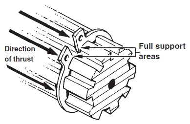
- Make sure the distance collar is seated within the ring gear.
- Apply molybdenum disulfide grease to the splines of the ring gear and to the splines on the rear wheel hub.
- Make sure the ring gear splines mesh with those on the rear wheel.
Inspection
- Inspect the gearcase for any external damage.
- Make sure the oil filler bolt and drain bolt are in good condition.
- Inspect the internal splines in the ring gear. If there is excessive wear or damage, replace the gear coupling.
- Check the oil seal for leaks or signs of damage. If necessary, replace the oil seal as follows:
- Pry the oil seal from the ring gear bearing housing.
- Lubricate the new oil seal with lithium soap grease, and set it in place.
- Use a driver of a socket that matches the diameter of the oil seal to drive the seal until it is seated in the housing.
For more Manuals by Yamaha, visit ManualsLibraryy
Yamaha V star 1100 Bike-FAQs
How far can the Yamaha V Star 1100 go on a full tank?
On average, the V Star 1100 can travel between 110 to 125 miles on the main tank. With reserve fuel included, the total range is around 167 miles, depending on riding habits.
How many gears does the V Star 1100 have?
The bike features a 5-speed manual transmission, delivering smooth power from its 1063cc V-twin engine.
Is the Yamaha V Star 1100 air-cooled?
Yes, it uses an air-cooled V-twin engine, which adds to its classic cruiser style and reduces mechanical complexity.
How much oil does the V Star 1100 need?
1. With oil filter change: 3.3 quarts
2. Without oil filter change: 3.17 quarts
Check the oil level using the sight glass on the engine.
How long can a Yamaha V Star 1100 last?
With regular maintenance, it can last over 150,000 miles, potentially serving you well for 30+ years, especially with average use (3,000–5,000 miles per year).
How heavy is the V Star 1100?
It weighs approximately 616 pounds with a full tank, which is typical for cruisers in its class.
How can I check if the oil level is correct?
Use the dipstick or sight glass. If the oil level is between the minimum and maximum marks, it’s fine. Add oil only if it’s below halfway.
What is the standard battery voltage for the V Star 1100?
The battery should read 12.5 to 12.8 volts when idle. If the voltage drops below 10.5 volts during startup, the battery may need replacement.


