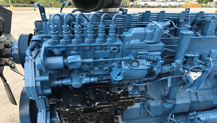
Navistar DT Engine 466
ENGINE SYSTEMS
Engine Identification
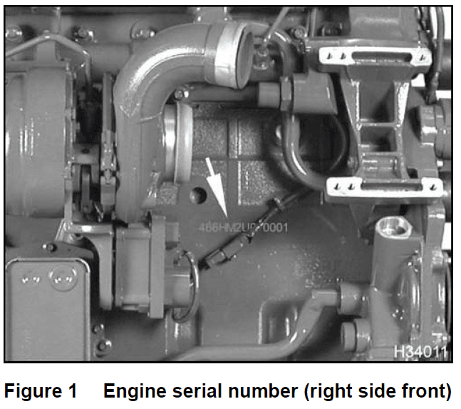
Engine Serial Number
Engine Serial Number Examples
- DT 466 engine: 466HM2UXXXXXXX
- DT 570 engine: 570HM2UXXXXXXX
- Engine Serial Number Codes
- 466 – Engine displacement
- 570 – Engine displacement
- H – Diesel, turbocharged, Charge Air Cooler (CAC), and electronically controlled
- M2 – Motor truck
- U – United States
- 7 digit suffix – Engine serial number sequence beginning with 2,000,000
Engine Component Location
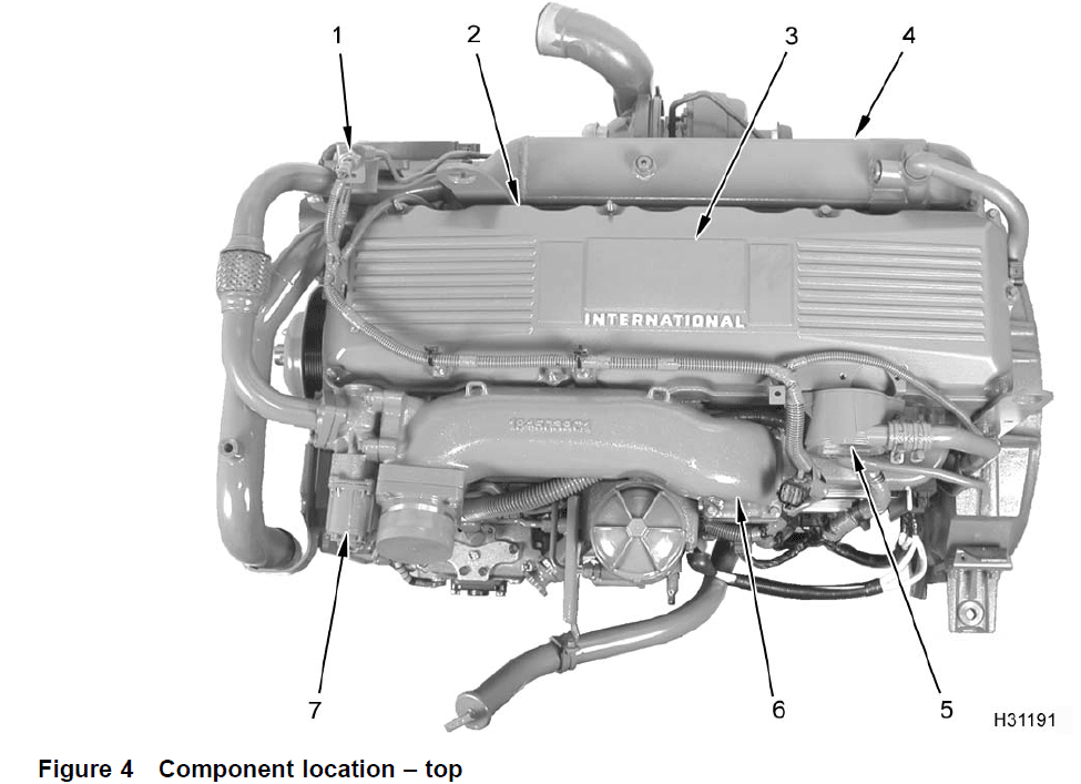
- Exhaust Back Pressure (EBP) sensor
- Valve cover
- Exhaust emission label (location)
- EGR cooler assembly
- Breather assembly
- Inlet and EGR mixer duct
- EGR control valve
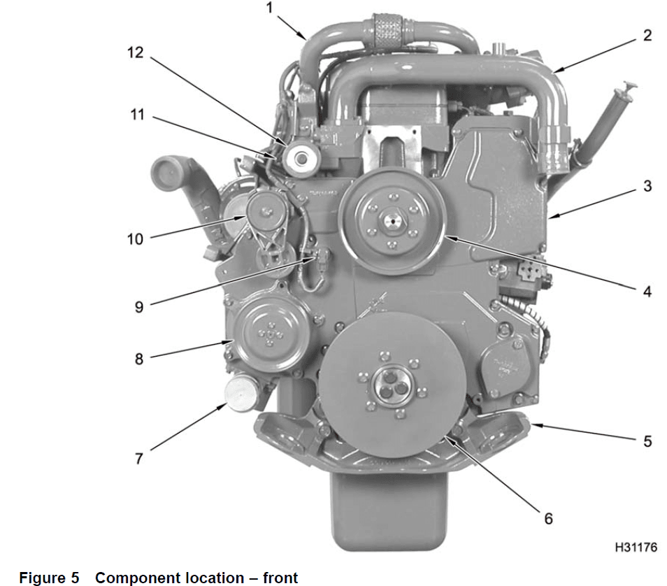
- Exhaust gas crossover (EGR cooler to EGR valve)
- Water outlet tube assembly (thermostat outlet)
- Front cover (front half)
- Fan drive pulley
- Engine mounting bracket (front)
- Vibration damper
- Water inlet elbow
- Water pump pulley
- Camshaft Position (CMP) sensor
- Auto tensioner assembly (belt)
- ECT sensor (location)
- Flat idler pulley assembly
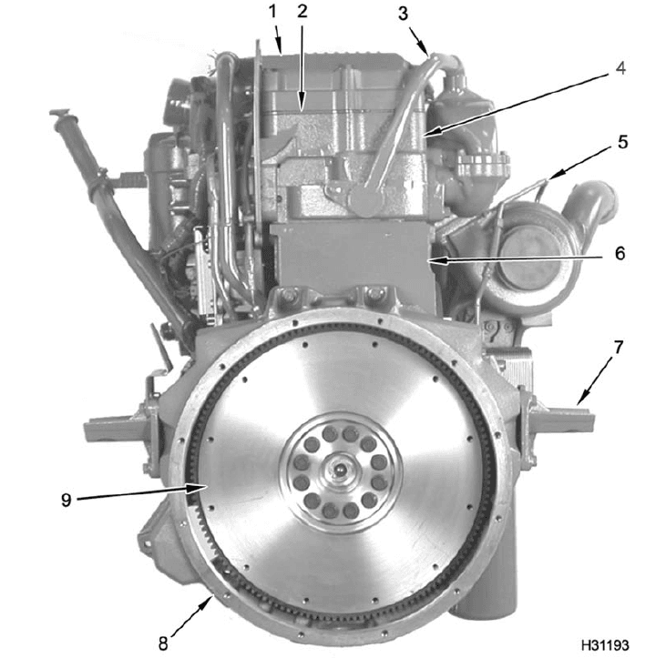
- Valve cover
- Valve cover gasket with pass-through connectors
- EGR cooler return tube assembly
- Cylinder head assembly
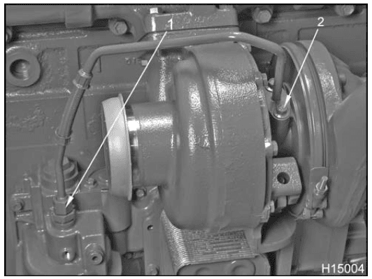
- Turbo oil inlet tube (supply)
- Crankcase
- Rear engine mount brackets (2)
- Flywheel housing
- Flywheel or flexplate assembly
Engine System Diagram
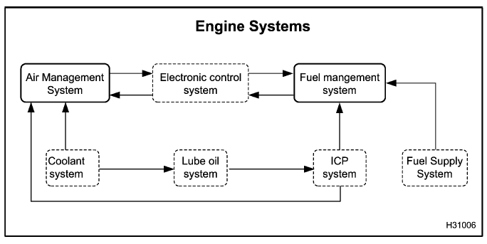
The primary engine systems are Air Management and Fuel Management which share some subsystems or have a subsystem that contributes to their operation.
- The Electronic Control system controls the Air Management System and Fuel Management System.
- The Coolant System provides heat transfer for EGR gases and lubrication oil.
- The Lube Oil System provides lubrication and heat transfer to engine components.
- The ICP system uses lube oil for hydraulic fluid to actuate the fuel injectors.
- The Fuel Supply System pressurizes fuel for transfer to the fuel injectors.
Operation and Function
The Electronic Control Module (ECM) monitors and controls engine performance to ensure maximum performance and adherence to emissions standards. The ECM has four primary functions:
- Provides Reference Voltage (VREF)
- Conditions input signals
- Processes and stores control strategies
- Controls actuators
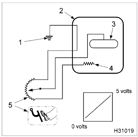
- Reference voltage (VREF)
- The ECM supplies a 5 volt VREF signal to input sensors in the electronic control system. By comparing the 5 volt VREF signal sent to the sensors with their respective returned signals, the ECM determines pressures, positions, and other variables important to engine and vehicle functions. The ECM supplies two independent circuits for VREF
- VREF A supplies 5 volts to engine sensors
- VREF B supplies 5 volts to vehicle sensors
- The ECM supplies a 5 volt VREF signal to input sensors in the electronic control system. By comparing the 5 volt VREF signal sent to the sensors with their respective returned signals, the ECM determines pressures, positions, and other variables important to engine and vehicle functions. The ECM supplies two independent circuits for VREF
- Signal conditioner
- The signal conditioner in the internal microprocessor converts analog signals to digital signals, squares up sine wave signals, or amplifies low-intensity signals to a level that the ECM microprocessor can process.
- Microprocessor
- The ECM microprocessor stores operating instructions (control strategies) and value tables (calibration parameters). The ECM compares stored
instructions and values with conditioned input values to determine the correct operating strategy for all engine operations. - Continuous calculations in the ECM occur at two different levels or speeds: Foreground and Background.
- Foreground calculations are much faster than background calculations and are normally more critical for engine operation. Engine speed control
is an example. - Background calculations are normally variables that change at a slower rates. Engine temperature is an example.
- Foreground calculations are much faster than background calculations and are normally more critical for engine operation. Engine speed control
- Diagnostic Trouble Codes (DTCs) are generated by the microprocessor, if inputs or conditions do not comply with expected values.
- Diagnostic strategies are also programmed into the ECM. Some strategies monitor inputs continuously and command the necessary outputs to achieve the correct performance of the engine
- The ECM microprocessor stores operating instructions (control strategies) and value tables (calibration parameters). The ECM compares stored
Microprocessor memory
- The ECM microprocessor includes Read Only Memory (ROM) and Random Access Memory (RAM).
ROM
- ROM stores permanent information for calibration tables and operating strategies. Permanently stored information cannot be changed or lost by turning the
ignition key OFF or when ECM power is interrupted. ROM includes the following:- Vehicle configuration, modes of operation, and options
- Engine Family Rating Code (EFRC)
- Engine warning and protection modes
RAM
- RAM stores temporary information for current engine conditions. Temporary information in RAM is lost when the ignition key is turned to OFF or when ECM
power is interrupted. RAM information includes the following:- Engine temperature
- Engine rpm
- Accelerator pedal position
Injection Drive Module (IDM)
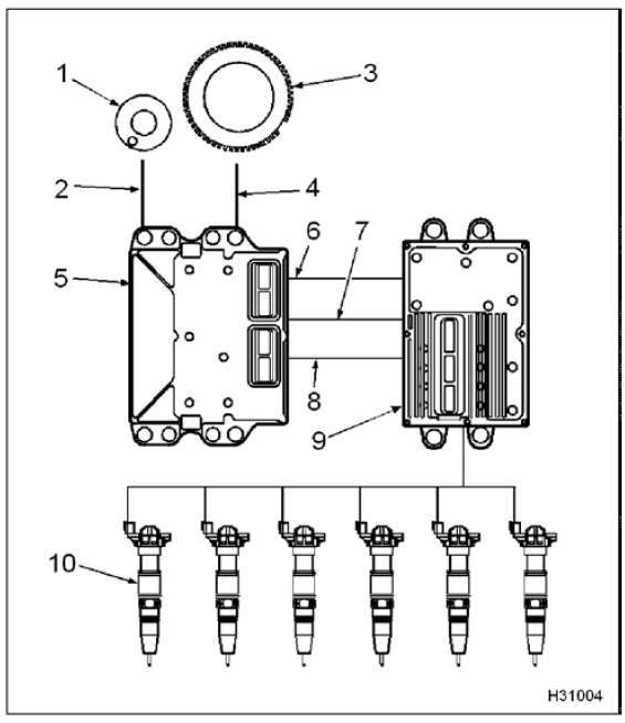
- Camshaft with peg
- Camshaft Position (CMP) signal
- Crankshaft position sensor timing disk
- Crankshaft Position (CKP) signal
- Electronic Control Module (ECM)
- Camshaft Position Output (CMPO) signal
- Crankshaft Position Output (CKPO) signal
- Controller Area Network (CAN 2) communication
- Injection Drive Module (IDM)
- Fuel injectors
The IDM has three functions:
- Electronic distributor for injectors
- Power source for injectors
- IDM and injector diagnostics
Engine and Vehicle Sensors
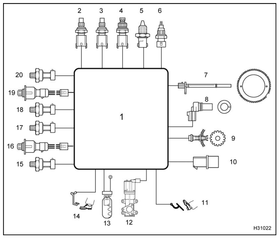
- Electronic Control Module (ECM)
- Engine Oil Temperature (EOT)
- Engine Coolant Temperature (ECT)
- Manifold Air Temperature (MAT)
- Intake Air Temperature (IAT)
- Water In Fuel (WIF) sensor
- Crankshaft Position (CKP)
- Camshaft Position (CMP)
- Vehicle Speed Sensor (VSS)
- Barometric Absolute Pressure (BAP)
- Accelerator Position Sensor (APS)
- Exhaust Gas Recirculation valve Position (EGRP)
- Engine Coolant Level (ECL)
- Driveline Disengagement Switch (DDS)
- Manifold Absolute Pressure (MAP)
- Brake Control Pressure (BCP)
- Engine Oil Pressure (EOP)
- Engine Fuel Pressure (EFP) sensor
- Injection Control Pressure (ICP)
- Exhaust Back Pressure (EBP)
Engine Oil Temperature (EOT)
- The ECM monitors the EOT signal to control fuel quantity and timing when operating the engine. The EOT signal allows the ECM and IDM to compensate for differences in oil viscosity for temperature changes. This ensures that power and torque are available for all operating conditions. The EOT sensor is installed in the rear of the front cover, and outboard of the high-pressure oil pump assembly.
Intake Air Temperature (IAT)
- The ECM monitors the IAT signal to control timing and fuel rate during cold starts. The IAT sensor is chassis mounted on the air filter housing.
Barometric Absolute Pressure (BAP)
- The ECM monitors the BAP signal to determine altitude, adjust timing, fuel quantity, and inlet air heater operation. The BAP sensor is located in the cab.
Exhaust Back Pressure (EBP)
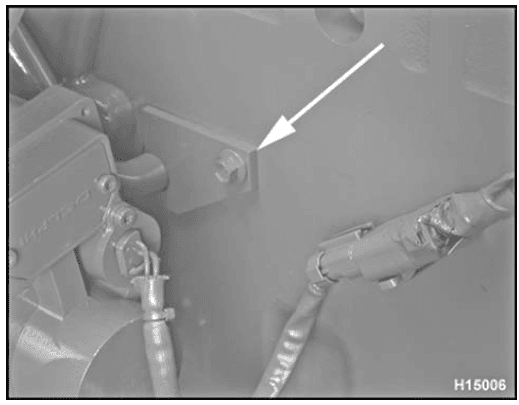
- The EBP sensor measures exhaust back pressure so that the ECM can control the VGT and EGR systems. The sensor provides feedback to the ECM for closed loop control of the Variable Geometry Turbocharger (VGT). The EBP sensor is installed in a bracket mounted on the water supply housing (Freon® compressor bracket).
Engine Fuel Pressure (EFP)
- The ECM uses the EFP sensor signal to monitor engine fuel pressure and give an indication when the fuel filter needs to be changed. The EFP sensor is installed in the rear of the fuel filter assembly (crankcase side).
Engine Oil Pressure (EOP)
- The ECM monitors the EOP signal, and uses this information for the instrument panel pressure gauge and EWPS. The EOP sensor is installed in the left
side of the crankcase below and left of the fuel filter housing.
Crankshaft Position (CKP) sensor
- The CKP sensor provides the ECM with a signal that indicates crankshaft speed and position. As the crankshaft turns the CKP sensor detects a 60-tooth timing disk on the crankshaft. Teeth 59 and 60 are missing. By comparing the CKP signal with the CMP signal, the ECM calculates engine rpm and timing requirements. The CKP is installed in the top left side of the flywheel housing.
- NOTE: This long CKP sensor, used with International® DT 466, DT 570, and HT 570 diesel engines, is the Camshaft Position (CMP)sensor used with other International® diesel engines
Vehicle Speed Sensor (VSS)
- The VSS provides the ECM with transmission tail shaft speed by sensing the rotation of a 16-tooth gear on the rear of the transmission. The detected sine wave
signal (AC), received by the ECM, is used with tire size and axle ratio to calculate vehicle speed. The VSS is on left side of the transmission
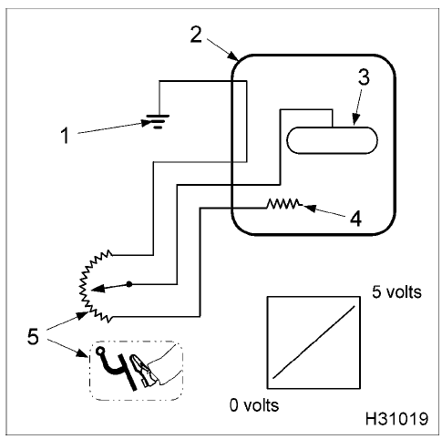
- Ground
- Electronic Control Module (ECM)
- Microprocessor
- Voltage reference (VREF)
- Accelerator Position Sensor (APS)
Engine Preparation
Cleaning the Engine
- Cap all openings to prevent water and degreased agents from entering any engine components internally.
- Cover any exposed electrical pin connectors and ECM, IDM, and EGR modules using plastic and duct tape.
- Use an appropriate detergent mixed in the correct ratio of water and apply to engine using a hot water pressure washer or similar cleaning equipment.
Draining Engine Fluids
- Place a coolant drain pan beneath the coolant drain plug. Remove coolant drain plug (M18) and O-ring from the bottom of the oil system module. Discard O-ring. Open radiator cap to allow system to drain quicker.
- After draining coolant, install new O-ring on plug and install in module. Torque plug to the standard torque value (General Torque Guidelines, page 445). Dispose of used coolant according to applicable laws

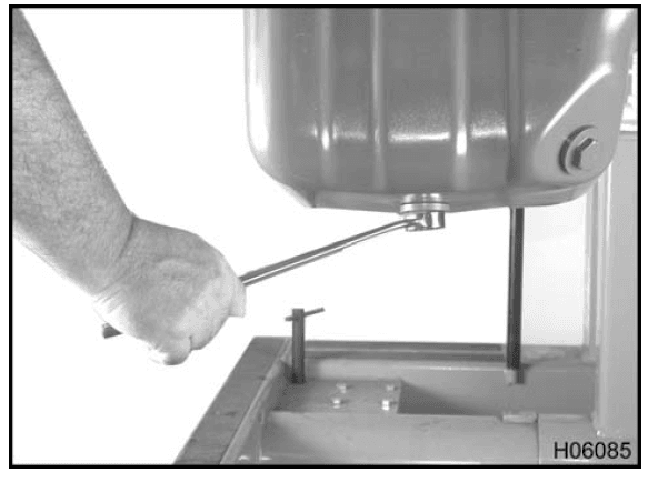
- Place a oil drain pan beneath the oil drain plug to collect the oil.
- Remove oil pan drain plug (M25) and O-ring. Drain engine oil and dispose of used engine oil according to applicable laws.
- Discard O-ring, inspect drain plug and replace if necessary. Place a new O-ring onto drain plug and install to oil pan. See special torque value (Table 3)
Turbocharger
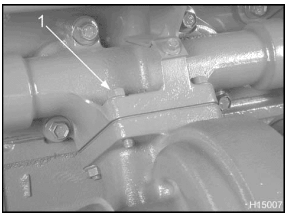
- NOTE: To aid in the disassembly of the turbocharger,loosen four nuts (M10) between 1/8 and 1/4 of a turn then tap each nut using a socket or flat punch
and hammer. This will knock the “peaks” of the stud threads off the “ramps” of the special Spiralock® nuts, thus allowing the nuts to unthread with considerable ease.
- Remove four nuts (M10 flange head) securing turbocharger assembly to exhaust manifold flange.
- Remove turbocharger assembly, oil drain tube, and turbo mounting O-ring from engine. Discard oil drain tube O-rings.
- Cap all openings on turbocharger assembly.
- NOTE: If plastic caps are not available, use duct tape to cover openings.
Oil Filter
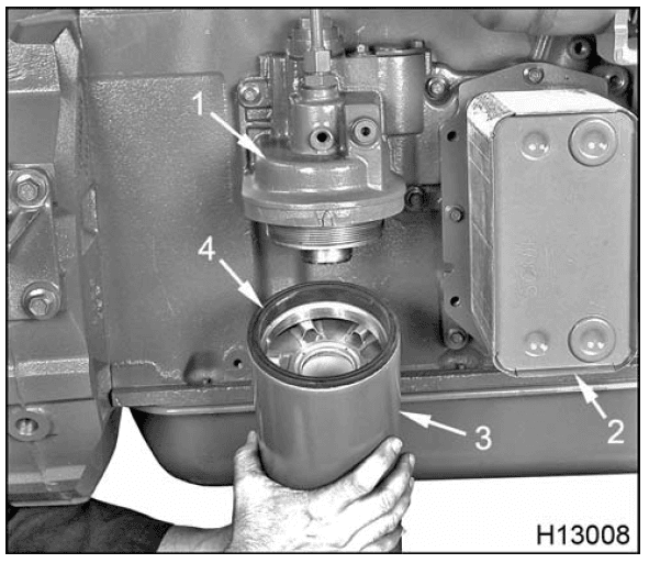
- Oil filter header
- Oil cooler
- Oil filter (spin-on)
- Oil filter gasket
- Remove oil filter from oil cooler filter header. Discard oil filter.
EVRT® ELECTRONICALLY CONTROLLED TURBOCHARGER
Description
- For the procedures in this manual, the term Variable Geometry Turbocharger (VGT) will be used. See (Variable Geometry Turbocharger (VGT), page 21) for complete description of the EVRT® electronically controlled turbocharger.
- This “EVRT® Electronically Controlled Turbocharger” section is for basic removal, exterior inspection and cleaning, and installation of the complete VGT
assembly. See additional specific procedures in Appendix E for the following VGT components: turbocharger actuator, turbocharger actuator linkage, turbocharger actuator flange and pivot shaft, and turbine vane assembly
Instruction Sheets in Appendix E
- Installation of Turbocharger Actuator (1171855R1Turbo Actuator Service Kit (SRA), page 497). This service kit provides instructions for the replacement of
the turbocharger actuator without the removal of the turbocharger from the engine - Installation of Turbocharger Actuator Linkage (1171908R1 Turbocharger VGT Linkage Kit,page499). This service kit provides instructions for the replacement of the turbocharger actuator linkage without removal of the turbocharger from the engine.
- Installation of Turbocharger Actuator Flange and Pivot Shaft (1171915R2 Turbocharger Actuator Flange and Pivot Shaft Kit, page 508). This service kit provides instructions for replacement of the internal turbocharger actuator flange and pivot shaft. These procedures require removal of the turbocharger from the engine.
- Cleaning Turbine Vane Assembly (1171913R1 Turbine Vane Assembly Cleaning Kit, page 503). This service kit provides instructions for cleaning the turbine vane area inside the housing when vanes become stuck due to excessive oil deposits. These procedures require removal of the turbocharger from the engine.
Cleaning
Turbocharger and Related Parts
- Use soap and water to clean piping between VGT and air cleaner assembly. Use filtered compressed air to dry piping.
- Use filtered compressed air to clean the air inlet piping and connecting hoses.
- Use a suitable solvent and a nylon brush to clean the oil inlet tube and oil drain tube. Use filtered compressed air to dry the tubes. Replace any damaged tubes.
- Clean the remaining gasket material from mounting surface of the turbine housing and exhaust manifold.
Installation
Variable Geometry Turbocharger (VGT) Assembly
- Position VGT on a workbench so the oil supply faces up.
- Prelube the VGT assembly by adding oil to the oil supply port while rotating the turbine shaft. Continue to add oil until oil comes out the oil drain port.
- Place a new turbocharger mounting gasket onto the turbocharger flange studs.
- Place a new O-ring onto each end of the turbocharger oil drain tube and lubricate with clean engine oil.
- CAUTION: To prevent serious personal injury, possible death, or damage to the engine or vehicle, exercise special care not to cut or damage oil drain
tube O-rings.
- CAUTION: To prevent serious personal injury, possible death, or damage to the engine or vehicle, exercise special care not to cut or damage oil drain
- Install oil drain tube into turbo charger side and then move the turbocharger and oil drain tube into cylinder block as a unit.

- Lift the VGT assembly onto engine and insert VGT mounting studs into the exhaust manifold flange.Install two new M10 Spiralock® nuts on the VGT
mounting studs. - Install two new M10 Spiralock® nuts on the exhaust manifold studs.
- Verify the oil drain tube is seated in the crankcase oil drain port.
- Tighten four M10 Spiralock® nuts to the special torque (Table 6).

- Align oil drain tube bracket with bolt (M8 x 16) and hole and tighten bolt to the standard torque value (General Torque Guidelines, page445).
- Place a new turbo oil inlet O-ring over oil inlet flange located on top of the VGT central housing.

- Nut
- Bolt, M8 x 20 (2)
- Thread two bolts (M8 x 20) through turbo oil inlet tube assembly at the top of the VGT. Do not tighten these bolts yet.
- Thread oil inlet tube assembly nut onto fitting located on top of oil filter header.
- Tighten two bolts (M8 x 20) at the top of the oil inlet tube assembly to the standard torque value (General Torque Guidelines, page445).
- Tighten oil inlet tube assembly nut to the standard torque value (General Torque Guidelines, page 445).
- Connect electrical harness to VGT actuator.
CYLINDER HEAD AND VALVE TRAIN
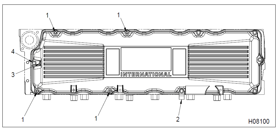
- Bolt / stud, M8 x 80 / 19 (4)
- Extension bracket
- Valve cover harness mounting bracket
- Bolt, M8 x 80 (6)
Removing Rocker Arm Assembly
- Remove high-pressure oil rail. See (Figure 640)

- Loosen all rocker arm adjusting screws and nuts. This will avoid possible valve train damage during installation.
- Loosen but do not remove 12 rocker shaft clamp bolts.
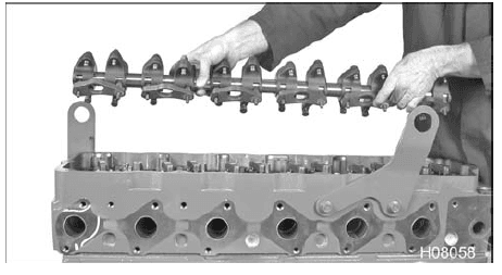
- Lift the rocker arm shaft assembly up and away from the cylinder head and set aside.
- NOTE: There are six nylon washers, one for each rocker shaft support, that are for assembly purposes. Make sure that you have these washers for installing the rocker arm shaft.
Removing Cylinder Head
CAUTION: To prevent engine damage, remove injectors before cylinder head removal (High-pressure Oil Rail Assembly, page346).
- Remove and discard 26 cylinder head mounting bolts (M15 x 180).

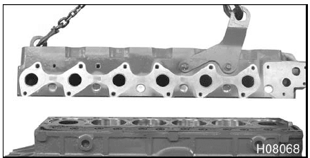
- Attach appropriate hoist and lifting hooks to lifting eyes. Carefully lift the cylinder head from the crankcase.
- After cylinder head been placed on a workbench surface, remove both lifting eyes and four bolts (M12 x 25) from cylinder head.
- NOTE: Place the cylinder head on wood blocks to protect the valves and bottom deck surface.

- NOTE: Place the cylinder head on wood blocks to protect the valves and bottom deck surface.
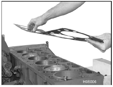
- Remove the cylinder head gasket from the crankcase. Discard the gasket.

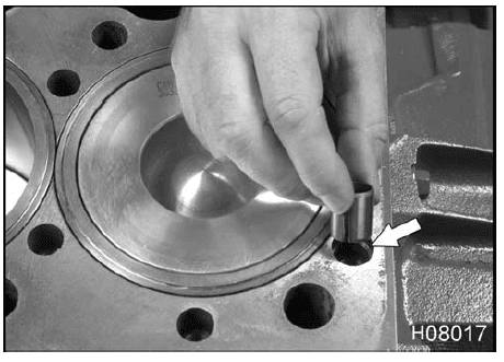
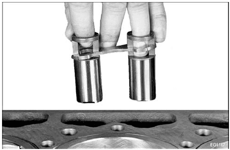
- Remove the alignment dowels from the top of the crankcase, only if damaged. Remove each roller tappet and guide from tappet bore and mark with cylinder number, valve association (intake or exhaust), and roller orientation.

Cleaning
Cylinder Head
CAUTION: To prevent engine damage, leave the valves installed within the cylinder head. This protects the valve seats during the cleaning process.
- Use a rotary wire brush or a sanding block with mineral spirits to remove any deposits and gasket material from the gasket surface of the cylinder head.
- Use an appropriately sized brush to clean all mounting bolt holes in the cylinder head.
- Wash rocker arm assemblies, hydraulic lifters, and push rods in a suitable solvent and dry them thoroughly. Replace any bolts that have damaged threads.
- CAUTION: To prevent engine damage, do not use chlorinated solvents on bolts or crankcase tapped holes. Parts should be clean, dry, and free of any
chemical residuals other than engine oil.
- CAUTION: To prevent engine damage, do not use chlorinated solvents on bolts or crankcase tapped holes. Parts should be clean, dry, and free of any
For more manuals by Navistar, visit ManualsLibraryy
Navistar DT Engine 466 Service-FAQs
What does “DT” stand for in DT466?
“DT” stands for Diesel Turbo, indicating that the engine is a turbocharged diesel engine.
What is a DT466 engine?
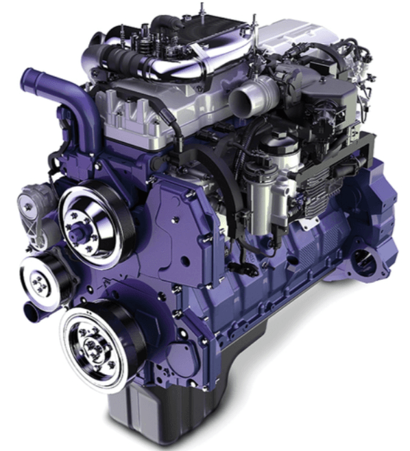
The DT466 is an inline 6-cylinder turbodiesel engine manufactured by International. It is commonly used in medium-duty vehicles like buses, box trucks, and some heavy-duty trucks.
How many liters is a DT466 engine?
The DT466 is a 7.6L (466 cubic inches) inline-six engine that produces up to 300 horsepower at 2,200 rpm and 860 lb-ft of torque at 1,300 rpm.
How long does a DT466 engine last?
With proper maintenance and care, a DT466 engine can last over 500,000 miles (800,000 kilometers).
How much oil does a DT466 engine hold?
DT466 engines from 1994 onward hold approximately 30 quarts of oil, including the filter. Older models may have a smaller oil capacity.
What is an engine service manual?
An engine service manual provides detailed instructions on maintaining and repairing an engine. It includes sections on disassembly and assembly, electrical systems, operational testing, and adjustments.
How do you check a service engine?
To check a service engine light:
Take the vehicle to a mechanic for a diagnostic test. Some shops waive the fee if you get the repairs done there.
Visit an auto parts store where they can read the code for free.
Use a scanner to read the code yourself.
What does “TBO” mean in engine terminology?
“TBO” stands for Time Between Overhauls, which is the recommended number of hours or time before an engine or component needs an overhaul.
What is the full form of DT in other contexts?
DT can also stand for “Digital Twin Spark ignition,” a system used in certain engines to improve combustion efficiency.
Why is the DT466 so widely used?
The DT466 is known for its durability, reliability, and suitability for medium- and heavy-duty applications, making it a popular choice for various vehicles across industries.

