
SegenSolar FOX ESS H3 12KW 3PH Hybrid Inverter
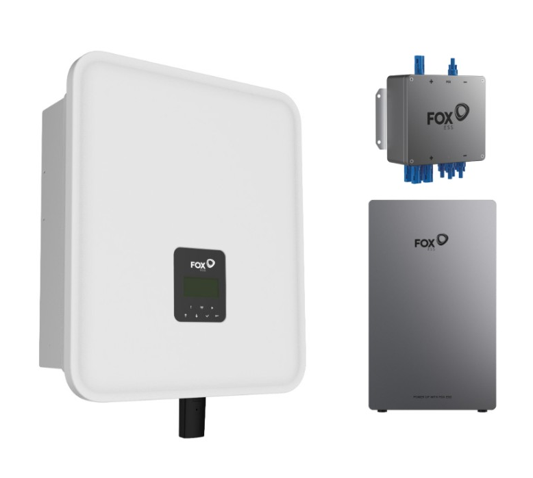
Packing List

Mounting Steps
- Step 1:
Please make sure the inverter will be installed at a proper distance as shown below.
- Step 2:
Select the installation location, place the bracket on the wall, and mark the hole positions.
- Step 3:
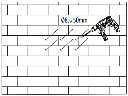
Drill the 6 holes with a φ8 drill bit. Depth: at least 50mm. Hammer the expansion tubes.
- Step 4:
Installing the Bracket. Screw the expansion bolts.
- Step 5:
Match the inverter with the wall bracket.
- Step 6:
Lock the screws on the side (Left and right). Make sure the inverter is firmly attached.
GRID Connection
Step 1
Prepare the AC wire.
Cable is a five-core cable with a diameter of less than 9~16 mm. The cross-sectional area of the wire is shown in the following table.

Step 2
Prepare the AC wire as shown in the picture.

Step 3
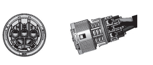
Separate the GRID connector into three parts as shown below. Insert the sleeve into the cable.

Step 4
Connect the cable to the GRID connector according to its polarity. Tighten it.

Step 5
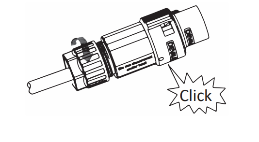
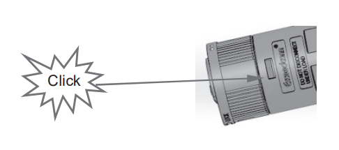
Push the threaded sleeve into the socket, and tighten up the cap on the terminal. Make sure to hear a “click” sound during this process.
Step 6
Push the threaded sleeve to connectto the terminal unl both are locked gently on the inverter. Make sure to hear a “click” sound during this process.

Notes:
H3/AC3 is a 3L-N-PE(TT, TN-C, TN-C-, S, and TN-S) system; an N line is required. Otherwise, a sw bus voltage fault will be triggered.
EPS Connection
EPS wiring diagram
For countries such as China, Germany, the Czech Republic, Italy, etc, please follow local wiring regulations.
This diagram is an example of an application in which neutral is separated from the PE in the distribution box.

For countries such as Australia, New Zealand, South Africa, etc, please follow local wiring regulations.
According to Australian safety requirements, the N cables of the GIRD side and EPS side must be connected. Otherwise, the EPS function will not work.

- Step 1:
Separate the EPS connector into three parts as shown below. Insert the sleeve into the cable.
- Step 2:
Connect the cable to the GRID connector according to its polarity. Tighten it.
- Step 3:
Push Housing into Body unyou hear a “click” sound.
- Step 4:
Put the sealing body and yarn trapper into the main body, and screw the lock nut into the main body.
- Step 5:
Insert the EPS connector into the EPS. For the rotaon the directionof the lock, please refer to the LOCK mark on the assembly. Notes:
If “sw bus volt fault” is reported under off-grid mode, please check the first subparagraph of secon 9 on page 55 of the Troubleshooting manual to resolve.
PV connection
PV Wiring (For H3 Only)
- Step 1:
Prepare PV wire. Choose 12 AWG wire to connect the PV module. Trim 6mm of insulation from the wire end.
- Step 2:
Separate the PV connector as shown below.
- Step 3:
To insert a terminal. Press the wire and terminal gently with a wire clamp. Rivet terminal. Ensure the concentricity of the metal parts and cable at the same level. Crimped metal parts and cable pull tension 2310N.
- Step 4:
Insert the pin into the male or female plug. Unl hear a “click”. Tighten the nut on the terminal.
BAT connection
- Step 1:
Prepare BAT wire.
We recommend using the original Bat-Inverter power cable and the communication cable from Baery’s accessory bag. If you require a longer cable, please contact our sales representative to purchase. - Step 2:
Connect the power line and communication line between the BMS and the inverter.
- Step 3:
Connect the grounding cable to ensure that all batteries are grounded. Wiring shall be connected in the sequence as shown below. The connection between the MS and the vert should be less than 10m.
Notes: The number of baery packs cannot be less than 3 pcs.
Meter connection
Meter Connection Diagram

- Step 1:
Insert L1/L2/L3/N wires and RS485A/B cable into the meter. Please refer to the meter wiring diagram on the side of the meter itself.
- Step 2:
Connect RS485A to pin 4 of the inverter METER/RS485 port. Connect RS485B to pin 3 of the inverter METER/RS485 port. Please use twisted pair cable.
This CT-Meter is not included in the package; please contact our sales department to purchase it if required.
- Step 1:
Insert L1/L2/L3/N wires, CT, and RS485A/B cable into the meter. Please refer to the meter wiring diagram on the side of the meter itself. During CT use, the direction of the CT arrow faces the grid. Notes: The 2,5,8 of the CT meter are connected to the three live wires L1, L2, and L3, respectively. .y CT to CT meter connection: CT S1/+ end access to the CT meter 1, 4, 7 ports; S2/- end access to the CT meter 3, 6, 9 ports. The following diagram shows the wiring diagram of a CT-to-CT meter:
- Step 2:
Connect RS485A to pin 4 of the inverter METER/RS485 port. Connect RS485B to pin 3 of the inverter METER/RS485 port. Please use twisted pair cable.
- Step 3:
The transformation rao seng of a CT meter needs to be consistent with the transformation rao of a CT meter. The transformationof the rao theeng method for a CT meter is as follows:
Grounding connection
Grounding Wiring
- Step 1:
Prepare ground wire.
- Step 2:
To insert the Earth terminal. Press the wire and terminal gently with a wire clamp.
- Step 3:
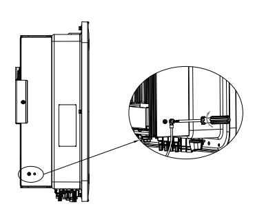
screw the ground screw with a screwdriver as shown below.
Firmware Update
Preparation
Please ensure the inverter is powered on with steady PV/BAT and AC power.
Please prepare a PC and a USB Disk.
Please note that the U-Disk shall be less than 32GB and its format is FAT16 or FAT32.
Please DO NOT apply a USB3.0 U-Disk on the SB port, the inverter USB port only supports USB2.0 U-disk.
- Step1:
Please contact our service support to get the updated files, and extract them into your U-Disk as follows:
update/master/ H3_E_Master_Vx.xx.bin
update/slave/ H3_E_Slave_Vx.xx.bin
update/manager/ H3_Manager_Vx_xx_E.bin
Note: Vx.xx is the ersversionmber. - Step 2:
Unscrew the waterproof lid and insert the U-disk into the “USB” port at the boom of the inverter. - Step 3:
The LCD will show the selectionon the menu. Then press up and down to select the one that you want to upgrade and press “OK” to confirm to upgrade. - Step 4:
Aer the upgrade is finished, pull out the U-disk. Screw the waterproof lid.
Inverter Start-Up

Please refer to the following steps to start up the inverter.
- Ensure the inverter is fixed well.
- Make sure the GRID and EPS wiring are completed.
- Make sure the PV wiring is connected well.
- Ensure the meter is securely connected.
- Ensure the battery is securely connected.
- Make sure the BMS buons and baery switch are on.
- Ensure accurate installation of the monitoring module on the inverter.
(Refer to the installation of the monitoring module) - Turn on the PV/DC switch (for Hybrid version only), AC breaker, EPS breaker, and battery breaker.
- Check whether each voltage is normal and within the operang range of the machine through the screen on the machine..e
- If the main page shows “switch off”, please long-press “√boom to quickly go to the START/STOP page and set it to start.
(Enter the sengs page, default password is ‘0000’).
Note:
- When starng inverter for the first me, the country code will be set by default to the local settings. Check if the country code is correct.
- Set me on the inverter using the buttonon or by using the APP.
Additional Functions
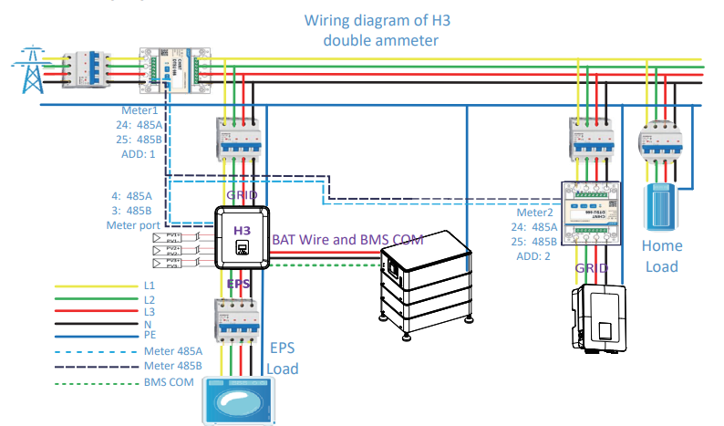
Dual meter function
A dual meter uses a second meter to detect the power generated by other power-generating equipment and synchronize it to the Fox ESS platform. The wiring diagram for the dual meter function is as follows.
Notes:
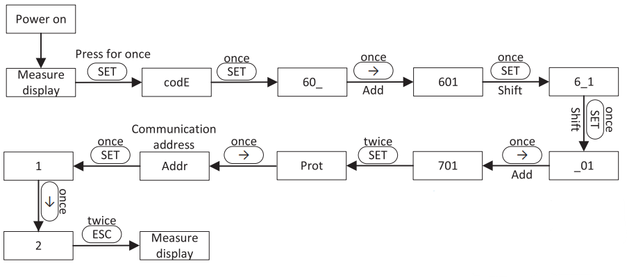
It is necessary to set the machine to enable the meter2 function and set the address of meter2 to 2.
The sequence method for turning on the second meter function of the machine is as follows:

The address set method for the second meter is as follows:
Off-grid and parallel functionon
The off-network and parallel operaon the function requires a matching off-network and parallel operaon the box EPS 3PH-4unit, which is a necessary equipment for off-network and parallel opera. At the same me, Master is set up to connect parallel1 and parallel2. The specific wiring diagram is as follows:

Notes:
When connecting parallel lines, please connect parallel1 to parallel2, and prohibit parallel1 from connectingto parallel1. Please refer to the User Manual for specific parallel details.
The specific seng method for seng machines that only connect to Parallel2 as hosts is as follows:

Introduction of EPS BOX PRO
The EPS BOX PRO is a wiring box for the H3. The box has a power distribuon a meter and a switching device that can add all house loads to the load port and can automatically switch the load power to the EPS port of the inverter in the event of an off-grid situation. Below is the reference wiring for the EPS BOX PRO.


WiFi Stick Installation
WiFi Stick Installation
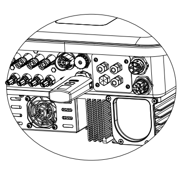
Alarm: The collector can only be plugged into the inverter, not any other device.
Step 1
For USB
Rotate the lock, make sure the triangle mark is on the front and centered. Plug the Smart WiFi into the WiFi/GPRS port under the boom (underside) of the inverter. Tighten the nut clockwise as follows.
Step 2
Power on the inverter (in accordance with the start-up procedure detailed in the inverter installation manual).
APP Installation
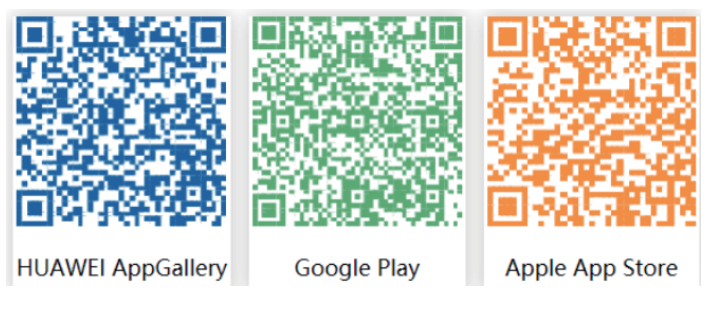
Scan the QR Code below to download and install the FoxCloud APP on your smartphone.
Configuration
Note: The module is powered on and started. Please wait for one minute to start the WiFi Config.
Web Configuraon
- Step 1:
Connect your mobile device to Smart WiFi. The SSID of the Smart WiFi is ‘W-xxxxx’ and the password is ‘mtmt2020’.
- Step 2:
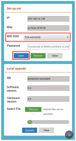
Aer connecting successfully. Open the browser and enter ‘192.168.1.1’ in the address bar at the top.
- Step 3:
Drop down the WiFi SSID menu to find the house router and input the house router’s password. Click ‘Save’.
APP Configuraon
- Step 1:
Open the APP, click “Local Distribuon Network” on the login page. Then click “Wifi Config”.
 Or sign in app, click on the “me” page. Then click “WiFi Config”.
- Step 2:
Please scan the “SN” on the collector.
- Step 3:
Connect your mobile device to Smart WiFi. The SSID of the Smart WiFi is ‘W-xxxxx’ and the password is ‘mtmt2020’.
- Step 4:
Please enter “Device WiFi” and “Password”, then click ‘OK’.
- Step 5:
Distributionon the network is successful.
Register An Account and Create A Plant
For Installer

Register An Account
- Step 1:
Please click ‘Sign Up’, enter the installer’s information to complete the installer account registration. Note: If you already have an installer/agent account, please press ‘Sign In’ and enter with your installer/agent account directly.
 - Step 2:
Select ‘Installer’ and enter the Installer name, then click ‘OK’. We suggest you complete all information to ensure apost-sales service.
Note:
Installer: The installer
Agent: The agent/distributor/installerof the company.
Great A Plant
- Step 1:
Open the APP, log in with your Installer/agent account.
- Step 2:
Press the ‘+’ icon on the homepage to add a plant. Press the scan icon next to the ‘Datalogger List’ to scan the QR code label on the front side of the Smart WiFi.
 Note: Aer starng the APP, it will pop up a message ‘Whether to allow positioning permissions’, please select ‘Allow’. For the PV Size, please fill in the actual capacity of the installed solar panels.
For more manuals by SegenSolar, visit ManualsLibraryy
SegenSolar FOX ESS H3 12KW 3PH Hybrid Inverter- FAQs
How does the Fox ESS hybrid inverter work?
The inverter converts direct current (DC) from solar panels or batteries into alternating current (AC) for home or business use. It also manages battery charging and discharging for efficient energy use.
What is a three-phase hybrid inverter?
A three-phase hybrid inverter distributes solar energy across three phases, making it suitable for larger homes, businesses, and industrial setups. It can also store excess energy in batteries for later use.
Are Fox ESS systems easy to install?
Yes. They feature a modular, plug-and-play design that allows quick installation. Additional batteries can be added in series for expanded storage.
Can Fox ESS inverters be installed outdoors?
Yes. These inverters are built for durability and are suitable for both indoor and outdoor installation.
What is the operating temperature range for Fox ESS batteries?
The batteries work reliably between -10°C and 50°C, ensuring safe performance in various climates.
Does a hybrid inverter work without a battery?
Yes, it can operate without a battery, but its functionality is limited. A battery allows energy storage and backup during power cuts.
How do I start or turn on the hybrid inverter?
Switch on the DC isolator, the DC isolator under the inverter, and then the AC isolator. The system will power up automatically.
How do I know if my inverter is working properly?
Check the LED indicators or display screen. A green light usually means normal operation, while a red blinking light signals a fault.






 Notes:


 The connection between the MS and the vert should be less than 10m.

 Notes: The 2,5,8 of the CT meter are connected to the three live wires L1, L2, and L3, respectively. .y CT to CT meter connection: CT S1/+ end access to the CT meter 1, 4, 7 ports; S2/- end access to the CT meter 3, 6, 9 ports. The following diagram shows the wiring diagram of a CT-to-CT meter:




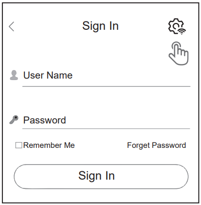 Then click “Wifi Config”.
 Or sign in app, click on the “me” page. Then click “WiFi Config”.


 Note: If you already have an installer/agent account, please press ‘Sign In’ and enter with your installer/agent account directly.


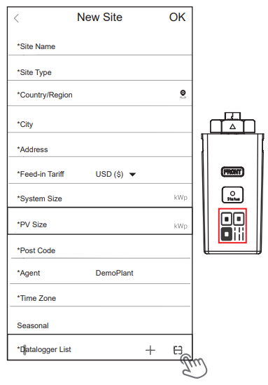 Note: Aer starng the APP, it will pop up a message ‘Whether to allow positioning permissions’, please select ‘Allow’. For the PV Size, please fill in the actual capacity of the installed solar panels.