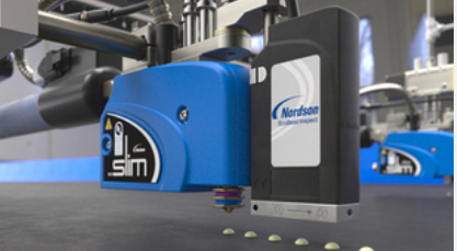
Nordson VersaBlue II Advanced Adhesive Melter
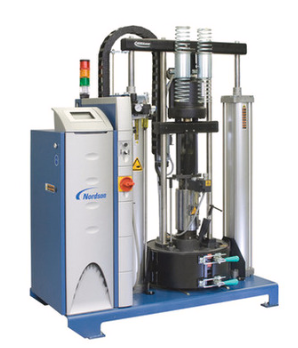
Description
Foreseeable Misuse
The melter may not be used under the following conditions:
- In a defective condition
- Without an insulation blanket and protective panels
- With the electrical cabinet door open
- With the tank lid open
- In a potentially explosive atmosphere
- If the melter does not comply with the applicable specifications
- When the values stated under Technical Data are not adhered to.
Electromagnetic Compatibility (EMC)
Concerning electromagnetic compatibility (EMC), the melter is intended for use in industrial applications. When operated in residential or commercial areas, the melter may cause interference with other electrical equipment, such as radios.
Introduction
This customer product manual describes VersaBlue® II melters. These melters can be configured as needed, meaning that each system is assembled to include the options selected by the customer when the system is purchased. If optional hardware is not installed, then the unique functionality of the optional hardware is not available for use. Options may be added to the melter only by Nordson at its plant in Lüneburg. Information on the configuration of the melter using the configuration code can be found later in this section.
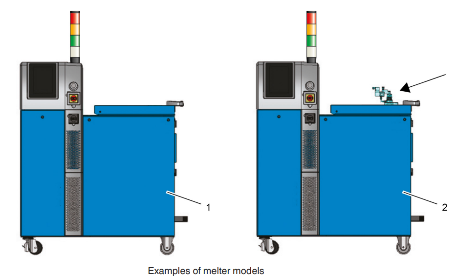
- Melter
- Melter with heated filling valve (arrow)
Front
The front is the side from which the melter is operated. This term is used as a reference for indications such as left/right and behind or back (side).
HMI (Human Machine Interface): Webserver interface between the melter and the operator. Example: The control panel on the melter or control devices such as a tablet, notebook, laptop, or desktop PC.
Master Control: The master control is the central melter interface. It brings together all of the subordinate systems, such as drives, temperature controllers, pressure sensors, etc.
VersaACM II: A VersaACM II or ACM (Auxiliary Control Module) is an additional electrical cabinet with its own customer product manual. Up to four ACMs can be connected to a melter. The ACM is controlled by the master control of the melter. It is available in two sizes: expanded and advanced. The size is a factor of the number of additional temperature channels and drives. An ACM in the VersaBlue® II system environment is called VAC in the software configuration code.
Structure of Melter
The following illustrations show the names and locations of the most important components of the melter. The configuration code indicates which of the components shown below are installed in the respective system; refer to the Melter Configuration Code.
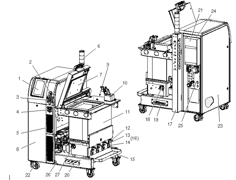
- Control panel
- LAN interface
- Main switch
- Motor switch
- Tower panel (air intake)
- Light tower with 5 colors
- Tank lid
- Protective panel
- Hose receptacles (electrical) (not visible here)
- Filling valve
- Tank (insulation blanket not shown)
- Hose connection
- Air relief valve
- Filter cartridge
- Drip tray
- Pressure control valve – depending on configuration
- Melter tower
- Recirculation hose connection
- 1st drawer for max. 4 pressure sensors
- 2nd drawer for max. 4 pressure sensors
- Heat exchanger
- Casters
- Electrical cabinet
- ID plate
- El. power connection/interfaces
- Tower panel fastener
- Tank drain valve
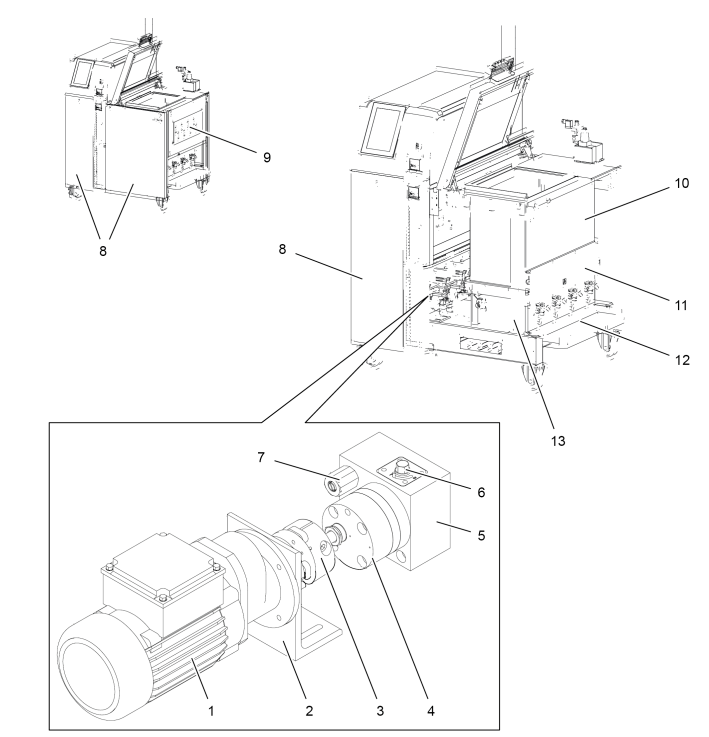
- Motor
- Motor bracket
- Coupling
- Gear pump (insulation blanket not shown)
- Bypass plate
- Tank isolation valve
- Bypass valve connection
- Protective panel
- Hose receptacles (electrical)
- Low melt (grid)
- Electrical equipment cover
- Adhesive drip tray
- High melt (reservoir)
Bypass Valve Plate
The bypass valve plate is located between the pump and the reservoir. The bypass valve plate contains the bypass valve and the tank isolation valve.
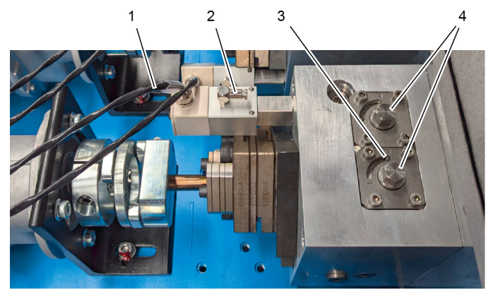
- Bypass valve: electronic monitoring
- Bypass valve: Pneumatic control connection
- Indication of tank isolation valve setting
- Screw head to open/close the tank isolation valve
The illustration shows the powertrain of the double-stream pump on the right and the bypass valve plate on the left. Because it is a double-stream pump, the bypass valve plate is equipped with two tank isolation valves.
Operating Elements
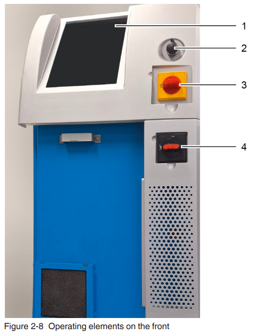
- Control panel
- LAN interface
- Main switch
- Service switch
There is another interface on the back; refer to USB Interface.
Control Panel
The melter control panel is a capacitive touchscreen. It is used to navigate and set up the melter as well as to adjust the system settings.
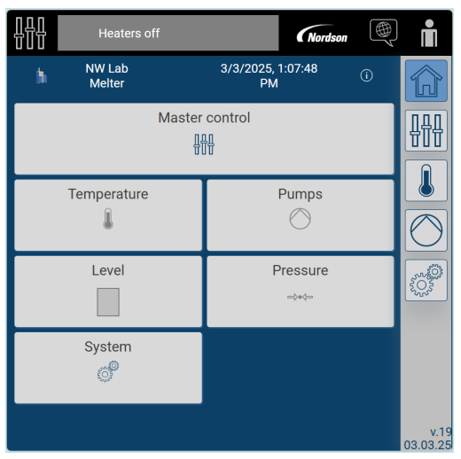
As with a smartphone, the screen can be operated with bare fingers, conductive gloves, or a conductive stylus. More information on the individual menus as well as on the operation of the touch screen can be found in the section Operation.
Hot Melt Application System
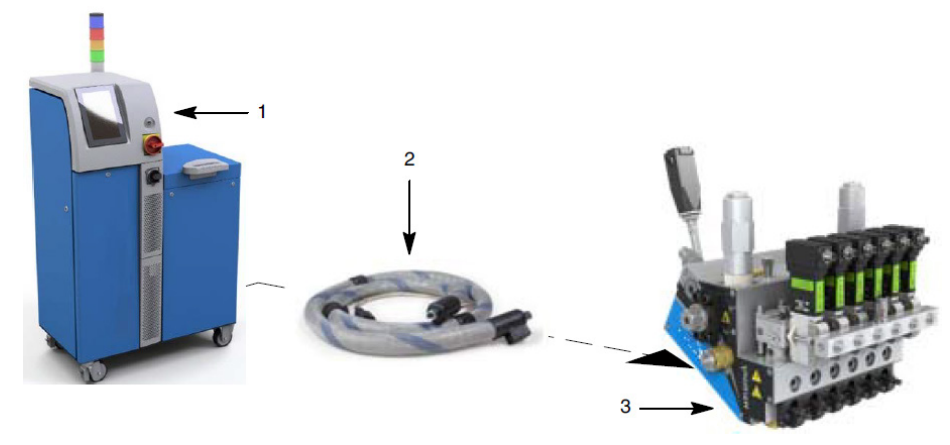
- Melter
- Hose
- Applicator
The Nordson melters are used in conjunction with hoses (2) and applicators (3) to create a hot melt application system. The melter liquefies solid-form hot melt and maintains the hot melt at the desired temperature. When the applicators are enabled, the melter pumps the melted adhesive through the hoses to the applicator nozzles, where it is then applied to the surface of a product or to a substrate.
Functioning
The following illustration provides an overview of the system and its setup.
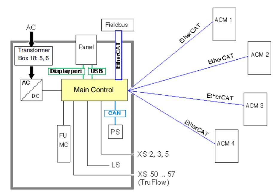
Legend for Illustration

24 V Power Supply: Depending on the configuration of the system, up to two 24 V power supply units can be installed in the melter. The power units supply voltage to the components inside the melter, such as: electrical cabinet fan, master control, control panel, and pressure sensors. The power supply for parts outside of the melter supplies voltage to the external pressure sensors.
Installation
Transport
- Refer to the section Technical Data for weight. Use only suitable transport devices.
- If possible, use the pallet that came with the melter and use angle brackets to fasten the melter.
- Use sturdy cardboard or a box to protect from damage.
- Protect from humidity and dust.
- Avoid jolts and vibrations.
Installation Requirements
Before installing the melter, ensure that the desired installation location provides the required clearances, environmental conditions, and utilities. Set up only in an environment that corresponds to the stated Degree of Protection (Refer to section Technical Data). Do not set up in a potentially explosive atmosphere! Protect from vibration.
Exhausting Adhesive Vapors
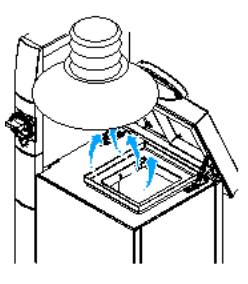
Ensure that adhesive fumes do not exceed the prescribed limits. Always observe the safety data sheet (MSDS) for the adhesive to be processed. Exhaust material vapors if necessary. Ensure sufficient ventilation of the installation location when the tank lid on the heated melter is opened.
Setting Up Melters with a Transformer
The transformer is located under the melter
- Keep cables and hoses out of the space under the melter.
- Position the melter such that air can circulate sufficiently under the melter.
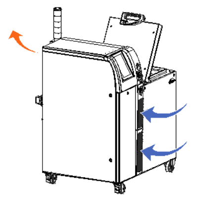
Electrical Cabinet Ventilation
Refer to Figure 3-5. The air is drawn in through the front panels of the tower, filtered, and then discharged again through the vent at the top of the back electrical cabinet panel. An air/air heat exchanger is configurable.
Power Supply
Before installing the melter, ensure that the melter will not be overloaded and that the plant’s electrical service is rated to handle the power required by the melter and the hoses and applicators that you plan to use. Refer to the section Technical Data for the loads of the various melters.
Considerations Regarding Installation Location
Some of the important factors that should be considered when assessing a location for potential installation of the melter:
- The maximum distance between the melter and the individual applicators is based on the maximum hose length permitted.
- Keep in mind the space needed for operation and maintenance.
- Position the melter such that it can be moved if the installation location is not spacious enough for maintenance.
- The melter must be installed away from areas with strong drafts or where sudden temperature changes occur.
- The melter must be installed where it will be in conformance with the ventilation requirements specified in the Safety Data Sheet for the hot melt being used. Use an exhaust hood if needed.
- The operator has to be able to work on the equipment, such as being able to reach the control panel and fill the tank.
Connecting Compressed Air Supply
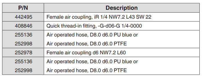
Accessories for Pneumatic Connection on Site
Setting Pressure
Bypass Control
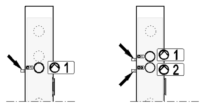
The pneumatic pressure control valve has a transmission ratio operating air pressure / adhesive pressure of 1:15. The arrows point to the handwheels of the individual pressure controllers. They are available only with the options Manual pneumatic pressure control and Bypass control.
Connecting Hoses and Applicators
VersaBlue® II adhesive melters are used along with hoses and applicators provided by Nordson. Depending on the respective configuration, up to eight hose/applicator pairs (= 16 temperature channels) can be connected to the melter. The temperature channels have to be taken into account when ordering heated filling valves or an air heater; also, some hoses require two temperature channels. The number of temperature control boards and hose receptacles installed in the melter determines how many hoses and applicators can be connected to the melter. If the permitted melter configuration has not been maximized, the number of retrofitting channels can be increased with a retrofitting kit.
Connecting Hoses
Comply with the following guidelines:
- Contact your Nordson representative for information on how to select the proper hose for the respective manufacturing process.
- Refer to the user guide and/or customer product manual supplied by Nordson, along with each hose. They contain essential information about routing and installing the hose.
- Save the plugs removed from the manifold. If a hose is later removed, a plug has to be inserted into the manifold.
- Use suitable hose connections. Hose connections are supplied along with the melter. Refer to the separate parts list if, e.g., other angles are needed.
Connecting Applicators
Observe the following:
- VersaBlue® II adhesive melters can be operated with Ni120 and Pt100 applicators supplied by Nordson.
- Contact your Nordson representative for information on how to select the proper Nordson applicator for the respective manufacturing process.
- The solenoid valves are not intended to be triggered via the hose. This is why the customer should handle valve control. If necessary, provide a separate signal line.
- Refer to the applicator customer product manual for installation information.
Melter Inputs and Outputs (I/O)
The inputs and outputs can be found on the back of the melter.
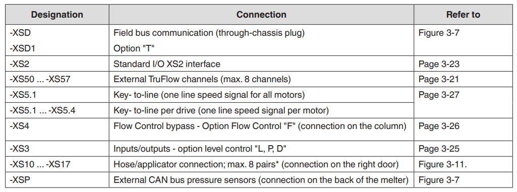
Interface XS50 to XS57: TruFlow inputs

Interface XS3: Level Control and Display
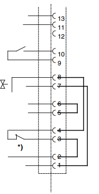
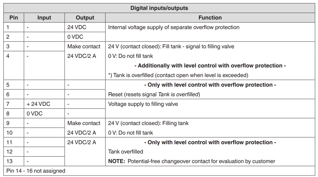
Setting Up the Melter
After physically installing the melter, it must be set up to support your manufacturing process. Melter setup consists of enabling or making changes to factory-set operating parameters that affect the use and function of the melter. The operating temperature (setpoint) of the tank and of each hose and applicator is specified during melter setup. The melter is shipped from the factory with the most commonly used operating parameters already set. The factory setup can be modified at any time to suit your manufacturing process.
Operation
Operator Level Tasks
The sequence of the tasks that the operator performs:
- Fill the melter tank.
- Start the melter for the first time.
- Operate the melter.
- Shut down the melter
Before proceeding with the next tasks, ensure that the melter is properly and completely installed and that it is connected.
Fill Melter Tank
Before filling the tank, confirm that the hot melt adhesive is compatible with the melter. For information on hot melt adhesives that should not be used in VersaBlue® II melters, refer to Intended Use in the section Description (section 2).
For melters with inert gas equipment (option): Ensure that the inert gas inlet hole is not clogged with adhesive.
Automatically: Automatic tank filling is performed, e.g., by a bulk melter connected with a hose to the optional filling valve. Level sensors in the tank start and stop the filling process.
Manually
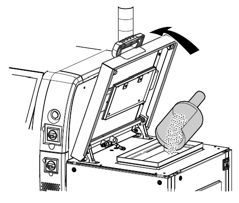
- Open the tank lid.
- Fill the tank with hot melt adhesive. Refer to Figure 4-2 to see the maximum level.
- Close the tank lid again when the tank has been filled.
Maximum Level
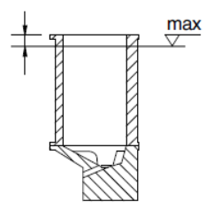
The level should not exceed 25 mm (1 inch) below the rim of the tank; this also applies to melters with the inert gas option (The inert gas is fed through two discharges in the tank lid). Adapt the maximum level to the adhesive dispensing speed. Feed adhesives sensitive to temperature quickly to prevent loss of quality.
Processes
- The system is booting.
- Backup is being created or loaded.
- The temperature unit is being changed.
- Alarm history is being deleted.
- Nordson reset is being performed.
- OPC UA is being activated/deactivated.
- The field bus error log is being deleted.
- Ethernet/IP IP address is being saved.
- Ethernet/IP IP address II is being saved.
- Defaults are being loaded.
- Customer recipe is being loaded.
- Customer recipe is being saved.
- The pressure sensor is being assigned or deselected.
- Software update is being performed.
- First system initialization is being performed.
- The initialization file is being created.
- Change to the control panel (e.g., date & time)
- License transaction is being performed.
- Other tasks
Master Control
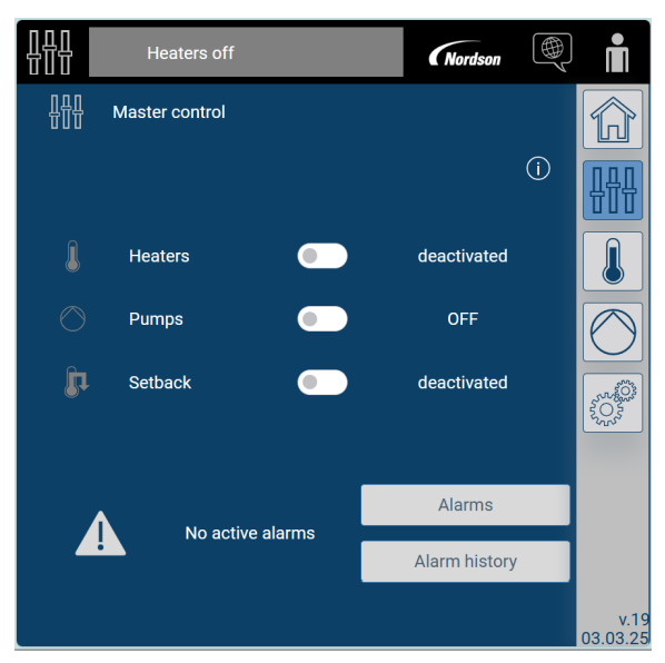
- Heaters off
- Master control
- Heaters
- Pumps
- Setback
- No active alarm
- Alarms
- Alarm history
A yellow icon and the message External melter control is deactivated! Indicates that all write access via the interfaces, such as XS2, field bus, and OPC UA, will be blocked. Read access is still possible.
Maintenance
Disable Remote Access
- Open the pop-up menu User management via the control panel.
- Touch Disable remote access to disable remote access.
Switch Motors and Secure Them to Prevent Them From Being Switched On Again
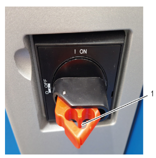
- Set the motor switch to 0/OFF.
- Use a lock to prevent the motor switch from being turned on again. There are holes (1) on the switch grip for the lock.
Relieve System (Adhesive) Pressure
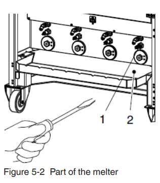
- Switch off the motor(s).
- Attach the drip tray (2) under the air relief valve (1) again, if necessary.
- Use a screwdriver to turn the air relief valve (1) screws counterclockwise and open the valves.
- Adhesive flows out of the air relief holes, and the melter is relieved of pressure.
- Use a screwdriver to turn the air relief valve screws clockwise and close the valves.
- Place a container under the nozzle(s) of the applicator/assembly handgun.
- Trigger the solenoid valve(s) electrically or manually, or pull the trigger of the assembly handgun. Repeat this procedure until no more adhesive flows out.
- Properly dispose of the collected adhesive according to local regulations.
Observe During Maintenance
Use Cleaning Agent
- Never use halogenated hydrocarbon solutions to clean components made of aluminum or to purge Nordson equipment. The strong chemical reaction can cause injury or death. Also, refer to the section Safety Instructions.
- Use only a cleaning agent recommended by the material manufacturer. Observe the Material Safety Data Sheet for the cleaning agent.
- Cleaning agent residue can be flushed out of the melter with new material before production begins again.
- Properly dispose of the cleaning agent according to local regulations.
Use Processing Materials
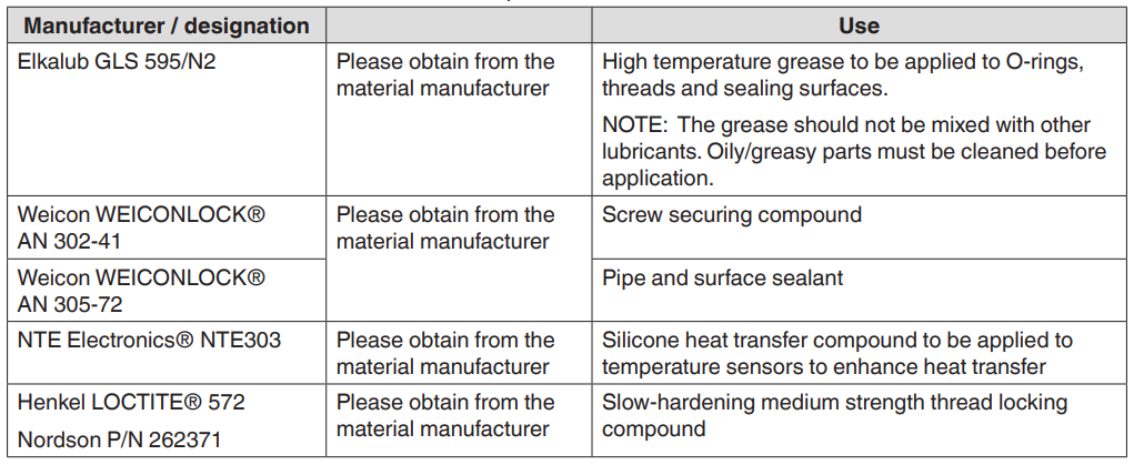
Replace Used Parts
If any connections are detached during maintenance, the following parts must always be replaced:
- Fastening materials
- Do not reuse fastening materials that hold together components where leakage may occur. Especially screws with a property class of 10.9 to 12.9.
- Self-locking materials, such as screw securing compound, etc., may only be used once.
- O-rings
- Always remove used (outer) O-rings when removing equipment.
- If there are no new O-rings available, the part with the old O- O-rings must be heated with a hot air fan until the adhesive softens before it can be screwed into place again.
Remove Outer Panel: To allow maintenance to the interior components, parts of the outer panel on the melter have to be removed. The panels can be removed or pivoted out. They can be opened using the included 6 mm square key.
Troubleshooting
Troubleshooting Checklist
Before starting systematic troubleshooting, check the following:
- Is the seven-day clock set correctly?
- Are all parameters set correctly?
- Is the interface wired correctly?
- In key-to-line mode: Is there a line speed signal provided?
- Do all plug connections have sufficient contact?
- Have circuit breakers been tripped?
- Could the fault have been caused by an external PLC?
- Are external, inductive loads (e.g., solenoid valves) equipped with recovery diodes?
- Are the terminating resistors correct? Also, check the hoses and applicators if no adhesive or too little adhesive is being fed. For example, check
- Temperature channel settings
- Is the filter on the applicator clogged?
- Is the system properly deaerated? With low grammage, check the hose length and pump size as well as the time required for purging.
- Is the correct voltage (usually 24 VDC) being supplied to the solenoid valve?
- Is the compressed air indicated in the customer product manual available, and is it reaching the solenoid valve?
- Are one or more control modules connected or clogged?
Terminating Resistors in CAN Bus: In each CAN bus system used, terminating resistors are needed at the last pressure sensor to function properly. When replacing parts, check the setting on the old part and set it the same on the new part. When retrofitting, the terminating resistor on the previously last node may have to be switched off or removed, to then switch it on or plug it in on the new last node. The last pressure sensor along the bus is equipped with a terminating resistor.
Refer to Figure 6-1.
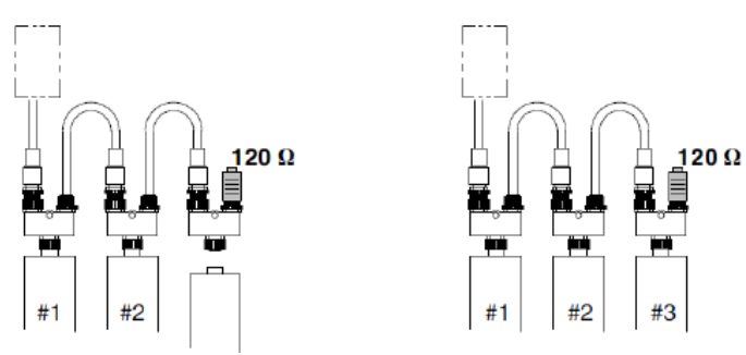
The Baud and CAN address settings are made automatically by the control unit.
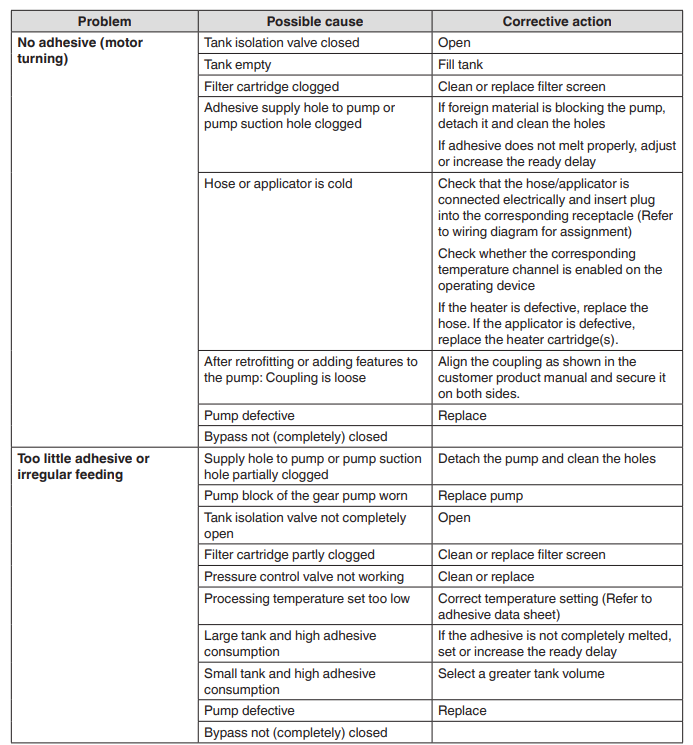
Troubleshooting Melter
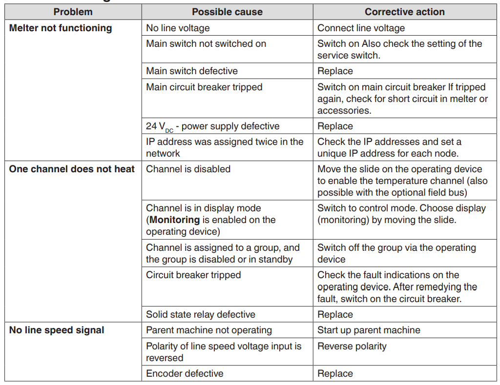
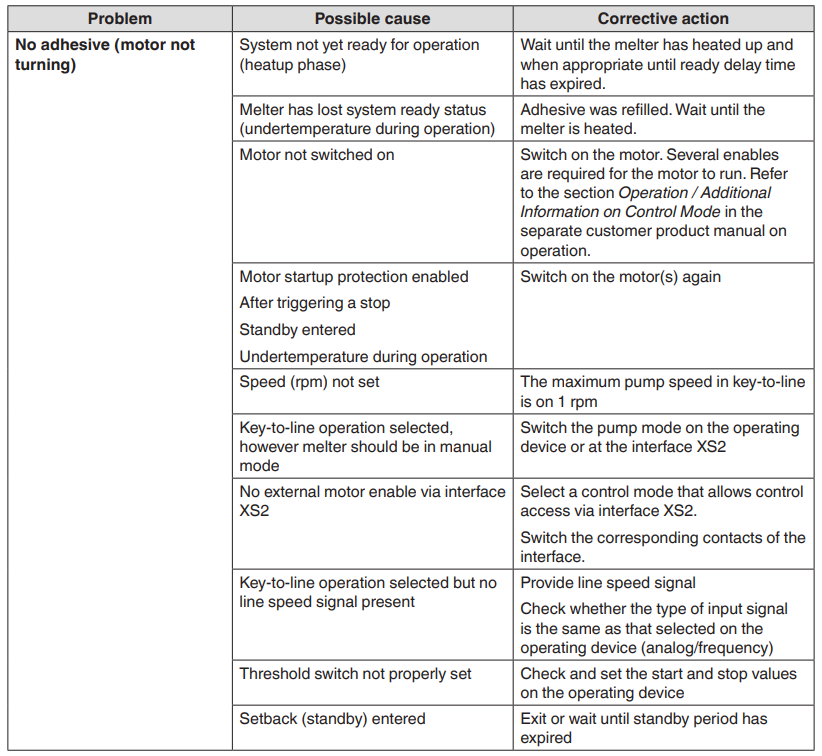
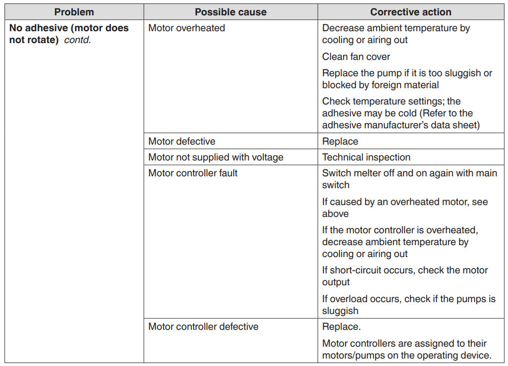
Troubleshooting Table
FOR MORE MANUALS BY NORDSON, VISIT MANUALSLIBRARYY
Nordson VersaBlue II Advanced Adhesive Melter-FAQs
What is the Nordson VersaBlue II used for?
It is an advanced adhesive melter designed for precise, reliable hot melt application in packaging, product assembly, and other industrial processes.
How do I start up the VersaBlue II melter?
Switch on the power, allow the unit to reach the programmed temperature, and confirm the system is pressurized before starting adhesive dispensing.
What type of adhesives can the VersaBlue II handle?
The unit is compatible with most hot melt adhesives, including EVA, polyolefin, and metallocene-based formulations. Always use clean, dry adhesives for best performance.
How do I set the temperature on the VersaBlue II?
Use the touchscreen control panel to enter your target temperature. The system will automatically heat the tank, hoses, and applicators to the set values.
Does the system allow remote monitoring?
Yes. The VersaBlue II supports network connectivity for remote operation, data tracking, and integration into production line controls.
What safety features are built into the VersaBlue II?
Perform basic cleaning weekly and schedule preventive maintenance as recommended. Regularly check filters, nozzles, and hoses to avoid adhesive buildup.
What safety features are built into the VersaBlue II?
It includes over-temperature protection, pressure relief systems, lockable covers, and warning indicators to help ensure safe operation.
How do I know if the adhesive level is low?
The system’s adhesive-level sensors will display alerts on the control panel and can also trigger warnings through network monitoring.

