
Altice Labs FGW-GR240BG Fiber Gateway 4×4

ALTICE LABS
All rights reserved. This document contains proprietary information belonging to Altice Labswhich is legally protected by copyright and industrial property rights and, as such, may not be copied, photocopied, reproduced, translated, or converted into electronic format, either partially or in its entirety, without prior written permission from Altice Labs. Nothing in this document shall be construed or interpreted as the granting of a license to make use of any software, information, or products referred to in the document.
This document is for information purposes only and does not constitute a legally binding offer. The communication of the information contained in this document shall not oblige Altice Labstoto to supply the products and services identified and described herein. Altice Labs reserves the right to effect changes to this document, at any time and without prior notice, and may not be held responsible for any inaccuracy in, or obsolescence of, the information, or for any losses or damage that may be incurred as a result of the use of the information.
Altice LabsRua Eng. José Ferreira Pinto Basto3810-106 Aveiro –Portugalhttp://www.alticelabs.com
Tel: +351 234 403 200
Fax: +351 234 424 723
This User Manual is applicable to the equipment FiberGateway Altice GR240BG with the FCC ID: 2ACJF-FGW-GR240BGFCC.
NOTICE
This device complies with FCC part 15 rules. Operation is subject to the following two conditions:
- This device may not cause harmful interference.
- This device must accept any interference, including interference that may cause undesired operation of the device.
Caution: Changes or modifications not expressly approved by the party responsible for compliance could void the authority to operate the equipment.
Note: This equipment has been tested and found to comply with the limits for a Class B digital device, under Part 15 of the FCC Rules. These limits are designed to provide reasonable protection against harmful interference in residential installation. This equipment generates, uses, and can radiate radio frequency energy and, if not installed and used by the instructions, may cause harmful interference to radio communications.
However, there is no guarantee that interference will not occur in a particular installation. If this equipment does cause harmful interference to radio or television reception, which can be determined by turning the equipment off and on, the user is encouraged to try to correct the interference by one or more of the following measures:
- Reorient or relocate the receiving antenna.
- Increase the separation between the equipment and the receiver.
- Connect the equipment to an outlet on a circuit different from that to which the receiver is connected.
- Consult the dealer or an experienced radio/TV technician for help.
This device meets the FCC requirements for RF exposure in public or uncontrolled environments.
RF Exposure Statement
Note: This transmitter must not be co-located or operated in conjunction with any other antenna or transmitter. This equipment should be installed and operated with a minimum distance of 8.3 inches (21cm) between the radiator and your body. This system has been evaluated for RF exposure for humans in reference to ANSI C 95.1 (American National Standards Institute) limits. The evaluation was based on FCC OET Bulletin 65C rev 01.01 in compliance with Part 2.1091 and Part 15.27. The minimum separation distance from the antenna to the general bystander is 8.3 inches (21cm) to maintain compliance.
Compliance with FCC requirement 15.407(c)
Data transmission is always initiated by software, which is passed down through the MAC, through the digital and analog baseband, and finally to the RF chip. Several special packets are initiated by the MAC. These are the only ways the digital baseband portion will turn on the RF transmitter, which then turns off at the end of the packet. Therefore, the transmitter will be ON only while one of the aforementioned packets is being transmitted. This device automatically discontinues transmission in case of either the absence of information to transmit or operational failure.
The FiberGateway is an Optical Terminal Equipment (ONT) unit for Passive Optical Networks (PON) termination in an FTTH (Fiber-To-The-Home) service delivery architecture. FiberGateway communicates with the OLT (Optical Line Terminal) for the PON side and with the customer’s premises for the client side. This equipment supports triple-play services -high-speed internet (HSI), voice (VoIP), video (IPTV), and WPS (Wi-Fi Protected Setup). The use of the GPON fiber access technology allows for a significant increase in service delivery when compared with traditional xDSL technologies.
The FiberGateway equipment technology is based on GEM (GPON Encapsulation Method) and complies with ITU-T G. 984. x. Recommendations like G.984.4 (OMCI) ensure interoperability with major GPON OLTvendors (BBF.247). These base functionalities, together with the support for bit rates of up to 2.5 Gbps (downstream) and 1.24 Gbps (upstream), an optical network splitting ratio of up to 1:64 in a single fiber, and a distance range of up to 60 km, make the GPON technology and the FiberGateway the most efficient option for passive optical network topologies when integrated service delivery is an issue.
Together with multi-vendor OLT interoperability (BBF.247 certified), other differentiated features of the FiberGateway product include the use of an embedded optical reflective component that increases probing resolution in the case of FTTH probing. The FiberGateway is also one of the first single-household integrated CPE solutions (ONT+GATEWAY). As opposed to the point-to-point architecture, in which there is one physical port per client in the Central Office, in the GPON point-to-multipoint architecture, there is only a single laser and photo-detector in the Central Office (CO) to serve up to 128 CPEs. The Optical Distribution Network is built by means of passive equipment modules with long-lived MTBF standards and very low OPEX.
FiberGateway Main Functionalities
The FiberGateway is aimed at customer premises and complies with the ITU-T G. 984. x recommendation in order to transport (over GPON) and deliver (to the premises domain) the full broadband service pack.
Broadband service applications are commonly referred to as below:
- High-speed internet (HSI);
- Voice (VoIP) services (SIP/MEGACO H.248);
- TV (IPTV)
- Wi-Fi. Combining the aforementioned services reinforces the multiplayer environment.
FiberGateway Application Scenario
The next figure shows a possible gateway scenario for FiberGateway equipment when in an FTT architecture.FTTx architecture.
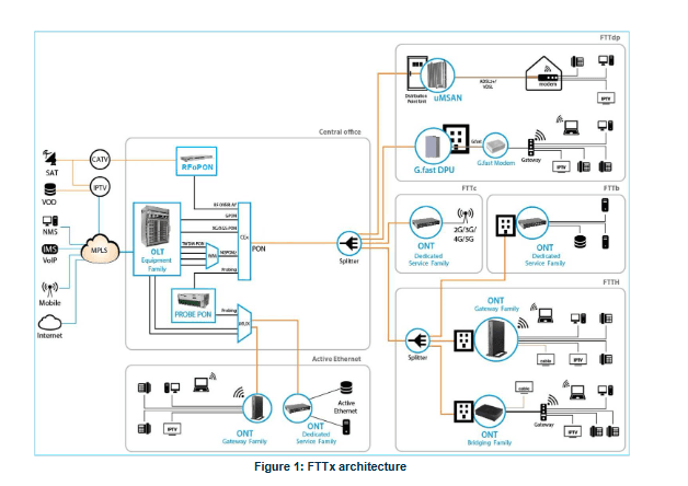
Interoperability
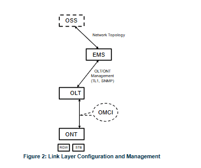
FiberGateway equipment complies with ITU-T G. 984. x. Recommendation as per G.984.4 (OMCI) ensuring multi-vendor OLT interoperability with major GPON OLT vendors, as defined in BBF.247 ONU certification program.BBF.247 ONU certification program certifies ONT link layer configuration and management protocol, OMCI, Figure 2, as defined by ITU-T G.984.3, ITU-T G.984.4, and ITU-T G.988.
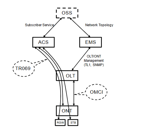
P-based services configuration and management are achieved using the TR-069 protocol as defined by the Broadband Forum. This procedure takes for granted that previously the link layer connectivity has been achieved.TR-069 is then transparent to the OLT since the TR-069 connections are established between the ACS and the ONTs, Figure 4. ONT gateway family types of equipment integrate gateway functionalities. Link layer configuration and management is achieved by the use of OMCI, while IP-based services (RG functionality and Voice over IP) are configured and managed.
Interfaces
- 4×10/100/1000Base T for Ethernet network connection (RJ45 connectors)
- 2x FXS channels (RJ11 connectors
- Wifi
o MIMO 4×4 @ 2.4GHz wireless interfaces (802.11 b/g/n)
o MIMO 4×4 @ 5 GHz wireless interfaces (802.11 a/n/ac)
- 1xUSB 2.0 Master for printer sharing, media sharing, and 3G/4G backup uplink
- Control switches for power and Wi-Fi
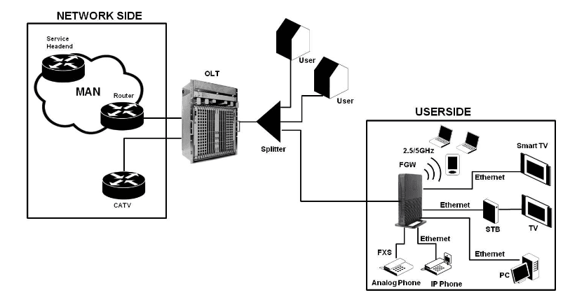
In the upstream direction, the FiberGateway is connected to the optical splitter and respectively to the OLT through the PON port to provide integrated access services through the service headend. In the downstream direction, the FiberGateway is connected to various terminals through the following
LAN-side ports to implement multi-play services:
- Four 10/100/1000M Base-T Ethernet ports, which can be connected to terminals such as PCs, STBs, and video phones to provide high-speed data and video services;
- Two FXS ports, which can be connected to telephone sets to provide VoIP services; |
- Four Wi-Fi antennas, which can connect to Wi-Fi terminals wirelessly to provide a secure and reliable high-speed wireless network;
- One USB port, which can be connected to a USB storage device to provide convenient storage and file-sharing services within a home network.
The communication between client equipment (ONT) and the ISP access routers (MAN edge) is made by an optical fiber-based passive architecture (ITU-T G.984 Recommendation). The GPON network acts as a Layer 2 Ethernet metropolitan network. Several transmission containers (T-CONT) are assigned to each user. Each T-CONT has an associated GEM port, and each GEM port has a VLAN identifier and an 802.1p priority level. The ONT classifies the traffic depending on the VLAN and the marked priority and routes it over the corresponding T-CONT/GEM port. Thu,s for frame multiplexing, GEM and T-CONT ports are used for uplink, while the downlink only uses the GEM ports feature.
FiberGateway complies with Broadband Forum TR-142 Technical Report, which defines a framework for the remote configuration and management of IP-based services over PON (Passive Optical | Network) and fiber access technology. TR-142 framework uses TR-069, which is the protocol of choice for the remote management and configuration of IP services over PON and fiber access networks. TR-069 is intended to be used for the remote configuration and management of IP services running over ONT, as well as for some aspects of ONT management.
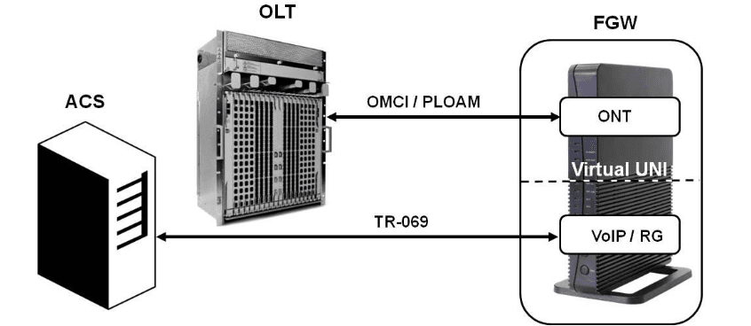
TR-142 framework defines a virtual UNI between the OMCI (ONT Management Control Interface) and ~~ TR-069 management domains. This framework allows PON CPE with L3 layer capabilities to be mass remotely configured, troubleshooted, and managed by an ACS (Auto Configuration Server) using TR-069 CPE WAN Management Protocol.
General Architecture
FiberGateway basic system architecture is presented hereafter.
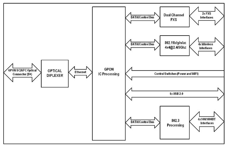
The GPON IC Processing unit is the core component inside FiberGateway. It is responsible for the interconnection and processing between client-side interfacing and the optical GPON Uplink interface.
GPON
The FiberGateway GPON layer, as G. 984. x uses 1490nm downstream and 1310nm upstream of the optical wavelength, with 2,483Gbps downstream and 1,244Gbps upstream by using an SC/APC protected optical connector.
Ethernet
Ethernet is the wired LAN technology and is defined in the IEEE 802.3 standard. At the OSI reference system, Ethernet is at the Data Link layer. In the FiberGateway equipment, both WAN and LAN types of physical interfaces are 10/100/1000BASE-T AUTO-MIX Ethernet type over RJ45 connectors.
IPTV
For the IPTV service, the FiberGateway also behaves like a Layer 2 bridging device. For this service, the FiberGateway has a specific GEM PORT for Multicast. This same GEM PORT is requested by the ~~ user to have access to the various IPTV channels. Every time a user requests a new channel, the FiberGateway will send the OLT an IGMP packet requesting that Channel. The FiberGateway is also responsible for implementing the snooping for the channels that the user requests.
Supported VoIP specifications
- Call control: SIPVIN2;
- T.38Faxrelay;
- FaxData bypass;
- Echo canceller;
- Echo canceller length;
- Jitter buffer;
- Caller ID generation;
- G711PCMU;
- G.711PCMA;
- G72;
- G72;
- G72;
- VAD and CNG;
- Caller ID and call waiting;
- RTPIRTCP packet encapsulation;
- RFC 2833 Support;
- In-band signaling detection and generation (DTMF, call progress tones).
- Automatic Tone generation (dial, busy, ring back, stutter, distinctive ring);
- 3-Way conferencing.
Supported interfaces
FiberGateway voice service provisioning could be made through OLT configurations over OMCI messages or could be downloaded (FTP) from the OLT up to the FiberGateway after its registration on the PON network. FiberGateway equipment can deliver Voice service over two types of interfaces:
Logical interface (VLAN encapsulation)
If the FiberGateway has no FXS ports and the VoIP service is transparently forwarded from the OLT up to the Home Gateway (and vice versa) within a previously defined voice VLAN. FiberGateway respects the defined priority and implements the traffic encapsulation from its own Ethernet interface | into a specific T-CONT/GEM-Port over the PON interface and up to the OLT equipment.
Physical interface (FXS ports)
The FiberGateway has physical RJ11 FXS interfaces. In this version of the FiberGateway equipment, voice interfaces are terminated in the equipment using FXS (RJ11) connections. The RJ11 analog terminals adapter function is auto/self-configured, integrated (analog/VolP), and associated with a defined SIP or Megaco (H.248) user.
Wi-Fi
FiberGateway Block Diagram
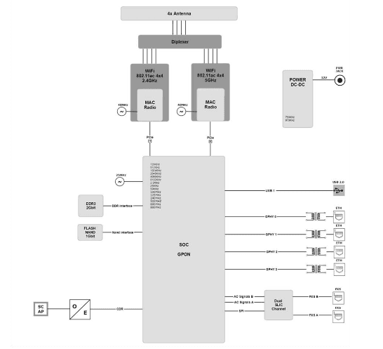
Fiber Gateway circuit block diagram is presented in the figure below showing all oscillators in the device and their frequencies, Figure 9. Intentional radiators in the circuit and radio signal path between circuit blocks are also shown.
Operational Description
The FiberGateway supports Wi-Fi, with Wi-Fi interfaces operating in the 2.4GHz and 5GHz frequencies The FiberGateway complies with the following standards:
- IEEE 802.11a (5GHz, up to 54 Mbps)
- IEEE 802.11b (2.4GHz, up to 11 Mbps)
- IEEE 802.119 b (2.4GHz, up to 54 Mbps)
- IEEE 802.11n (2.4GHz and 5 GHz, up to 600 Mbps)
- IEEE 802.11ac (5GHz, up to 1733 Mbps)
The ONT supports the following features:
wireless security
- WEP encryption (64/128 bits)
- WPA (Wireless Protected Access) TKIP
- WPA2 AES
- WPA2 mixed
- 802.1x Authentication
- External RADIUS Authentication
- Client access control through media access control (MAC) filter
- Dynamic cryptography (TKIP and AES)
- Multiple SSIDs Profiles
- WPS (Pushbutton and PIN entry)
Interfaces and features
- Dualband, concurrent mode 2.4GHz plus 5GHz via internal Wi-Fi antennas,
- Compliant with IEEE 802.11 a/b/g/n/ac and with 4×4 MIMO
- Up to 34 dBm EIRP both in the 2.4 GHz and in the 5 GHz
- Channel Bandwidth: 20, 40, 80, 80+80, 160
- Support of zero wait for dynamic frequency selection (DFS): 4×4 with weather radar detection
- Multi-User MIMO for better performance per user
Data Rates
- 802.11a:6,9,12,18,24,36,48,54 Mbps. :
- 802.11b:1,2,55,11 Mbps
- 802.11g:6,9,12,18,24,36,48,54 Mbps.
- 802.11n: up to 600 Mbps.
- 802.11ac: up to 1733 Mbps
- 1024QAM (2.4GHz) : up to 1000 Mbps
- 1024QAM (5GHz) : up to 2166 Mbps.
Antennas
- 4×4 MIMO antennas
- Internal antennas with 4~5dBi antenna gain
Multiple QoS per VLAN
The FiberGateway supports 802.1p QoS per VLAN services in which several flows (one per allowed pbit) are embedded in the same VLAN. According to the applied configuration, the FiberGateway performs a per-flow QoS policy: dropping traffic marked with not-allowed bits and limiting to the configured value the data rate of the allowed flows. The FiberGateway performs transparent VLAN translation. It is transparent to upper-layer protocols, such as ARP, RIP, DHCP, IGMP, PPP, etc.
Policing/Rate Limiting
Downstream QoS
The OLT system supports traffic classification at the ingress ports (ETH, LAGS, PON, etc) based on P-Bits, IP DSCP, and IP. The OLT system provides several QoS mechanisms that can be targeted to the flow characterized by one or two VLANs according to the type of service or can be targeted to the packet priority, where each p-bit/DSCP is mapped in one of eight queues of each port. Each OLT port is associated with eight queues, for each of these queues is possible to configure the p-bit mapping in one of the queues, the scheduler type (Strict Priority or Weighted Fair Queuing), and the minimum and maximum bandwidth of each queue.

In the downstream direction, Figure 10, the ingress traffic can be first classified. It passes by a policer and is configured to each ONT service, which is defined by one or two tags. It is remarked and policed per-Cos rate (port profile). After this, Network services (per VLAN) classification determines the PON port queue where packets will wait for a transmission opportunity, and can remark the CoS (P-bits in VLAN PCP). The traffic is put in a queue according to the p-bit/DSCP->Traffic Class mapping. Each of these Traffic Classes is associated with a scheduler (WRR or SP) and a police. Queue congestion management is used to prevent the queue from overflowing and is performed based on Tail Drop or WRED. Each queue is served by either a priority or weighted scheduler and is rate-controlled. Then, Traffic Classes to P-bit remarking is done, and the traffic flows to the GPON interface Destination ONU/ONT client service downstream profile defines traffic classless policing. The overall PON port may be limited to a percentage of its capacity.
Traffic arriving at the ONU/ONT will pass by a mapping block, which will map the traffic in one of the eight queues according to the p-bits; these queues have a Strict Priority scheduler in order to guarantee that the most prioritized traffic passes first (Figure 10.
General Features
GPON is a point-to-multipoint passive optical network in which unpowered optical splitters are used to enable a single optical fiber to serve multiple premises. A PON consists of an optical line terminal (OLT) at the central office and a number of optical network terminals (ONTs) at the customer premises. Downstream signals are broadcast to all premises sharing multiple fibers. Encryption can prevent eavesdropping. Upstream signals are combined using a multiple access protocol (Time Division Multiple Access -TDMA). The OLT queues data to the various ONT terminals to provide time slot assignments for upstream communication. It shows a scenario for a multi-service user domain basic architecture through a network.OSSEMSOLTONTRGWSTBACSTR069OMCINetwor TopologySubscriber ServiceOLT/ONTManagement(TL1, SNMP).
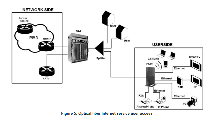
In the upstream direction, the FiberGateway is connected to the optical splitter and, respectively to the OLT through the PON port to provide integrated access services through the service headend. In the downstream direction, the FiberGateway is connected to various terminals through the following LAN-side ports to implement multi-play services:
- Four 10/100/1000M Base-T Ethernet ports, which can be connected to terminals such as PCs, STBs, and video phones to provide high-speed data and video services;
- Two FXS ports, which can be connected to telephone sets to provide VoIP services;
- Four Wi-Fi antennas, which can connect to Wi-Fi terminals wirelessly to provide a secure and reliable high-speed wireless network;
- One USB port can be connected to a USB storage device to provide convenient storage and file-sharing services within a home network.
For more manuals of Altice Labs, visit ManualsLibraryy.
Altice Labs FGW-GR240BG Fiber Gateway 4×4-FAQs
What is the Altice Labs FGW-GR240BG Fiber Gateway used for?
The FGW-GR240BG is a fiber gateway device that connects your home network to high-speed fiber internet. It supports both wired and wireless connections and ensures efficient internet distribution across your devices.
How do I set up the FGW-GR240BG Fiber Gateway?
To set it up, connect the fiber cable to the optical port, plug in the power adapter, and turn on the device. Then, use a web browser to access the gateway’s interface for configuration using the default IP address, username, and password provided in the manual.
What are the default login credentials for the gateway?
The default IP address is typically 192.168.1.1. The default username and password are often both “admin”, unless changed by your service provider. Refer to the manual or label on the device for exact details.
How can I change my Wi-Fi name and password?
Log in to the web interface, go to the Wireless Settings section, and update your SSID (Wi-Fi name) and password. Don’t forget to save the changes before exiting.
Does the FGW-GR240BG support dual-band Wi-Fi?
Yes, it supports dual-band Wi-Fi with 2.4GHz and 5GHz frequencies, allowing better speed and reduced interference for connected devices.
How many Ethernet ports are available on this gateway?
The FGW-GR240BG comes with four Gigabit Ethernet LAN ports for high-speed wired connections.
How can I reset the gateway to factory settings?
To perform a factory reset, press and hold the reset button on the back of the device for about 10 seconds until the LEDs blink. This will restore all settings to default.
Is remote management available for the FGW-GR240BG?
Yes, remote management features may be available depending on your service provider’s configuration. You may need to enable it through the web interface.
How do I check if the gateway is connected to the internet?
Check the LED indicators on the front panel. A steady green light on the internet/LOS (Loss of Signal) indicator usually means the connection is active.

