Honeywell 6700 Silent Knight Fire Alarm Control Panel
Introduction
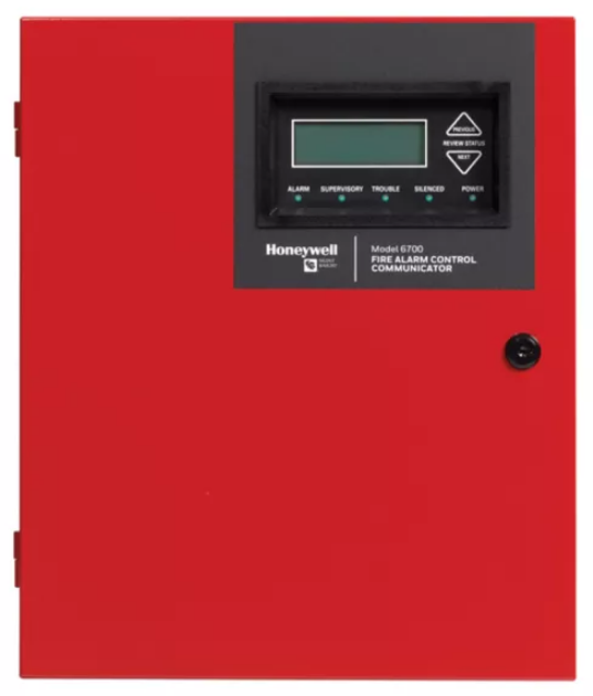
The 6700 Fire Alarm Control / Communicator is an Addressable Fire Alarm Control System that meets the requirements of UL 864 10th Edition Standard.
Basic System Overview
Hardware Features
- The 6700 has one built-in signaling line circuit (SLC) that supports 50 SK detectors and 50 SK modules or 50 SD devices.
- The 6700 is capable of outputting 2.5A of output power during an alarm activation through 2 sets of terminals for the notification appliance circuits or an auxiliary application. Each circuit is power-limited and can source up to 2.5A during an alarm activation. The constant auxiliary power load must not exceed 1A for normal standby.
- Built-in dual phone line, digital alarm communicator/transmitter (DACT), IP, or optional cellular technologies.
- Reports events to the central station by point or by zone.
- UL Listed for pre-action and deluge releasing systems.
- Two general-purpose Form C programmable relays.
- One Form C Trouble Relay.
- Basic system operation can be performed from the onboard or any remote annunciator.
- Up to 20 user profiles can be programmed, each having a custom Access Code and Main Menu items.
- Can be used with any combination of up to 8 Model 5860, 6860, or 6855 Remote LCD Annunciators (sold separately).
- Can be used with model 5865-3, 5865-4, and 5880 in any combination for a total of eight devices on one control panel.
- Printing of the event log is available through the Model 5824 serial/parallel printer interface module.
- 125 software zones, 125 Output Groups.
- Add four Notification/Auxiliary power circuits with each 5496 NAC Expander. See note below.
Software Features
- Advanced smoke detector features:
- Automatic drift compensation
- Maintenance alert region
- Point status meets calibrated smoke test requirements for NFPA 72
- “JumpStart” feature for easy programming
- Non-volatile event history stores 1000 events
- A choice of output patterns available for notification outputs, including Temp 4, along with ANSI 3.41 temporal signal
- Built-in synchronization appliance support for AMSECO, Gentex, Wheelock, or System Sensor
Agency Listings, Approvals, and Requirements
Install and maintain this panel by NFPA 72. Detector spacing shall be done in accordance to NFPA 72. End-of -line relays and resistors shall be placed within the electrical box located at the end of the initiating circuit. Testing and maintenance should be performed in compliance with NFPA 72.
Federal Communications Commission (FCC)
The following information must be provided to the Telephone Company before the 6700 can be connected to the phone lines:
- Manufacturer: Honeywell Silent Knight
- Model Number: 6700
- FCC registration number: US: HS9AL10A2100
- Ringer equivalence: 1.0A
- Type of jack: RJ31X
- Facility Interface Codes: Loop Start: 02LS2
- Service Order Code: 9.0F
- This device may not be directly connected to the coin telephone or party line services.
- This device cannot be adjusted or repaired in the field. In case of trouble with the device, notify the installing company or return to: Honeywell Silent Knight 12 Clintonville Road Northford, CT 06472-1610 (203) 484-7161
- If the 6700 causes harm to the telephone network, the Telephone Company will notify the user in advance that temporary discontinuance of service may be required. If advance notice is not practical, the Telephone Company will notify the user as soon as possible. Users have the right to file complaints, if necessary, with the Federal Communications Commission.
- The Telephone Company may make changes in its facilities, equipment, operations, or procedures that could affect the operation of the equipment. If this happens, the Telephone Company will provide advance notice to allow you to make the necessary modifications to maintain uninterrupted service.
Prerequisites for Installation
This section of the Manual is intended to help you plan your tasks to facilitate a smooth installation. Please read this section thoroughly, especially if you are installing a 6700 panel for the first time.
Inventory
When the 6700 shipment is received, check that all the parts have been included in the shipment. The shipment consists of one of each of the following:
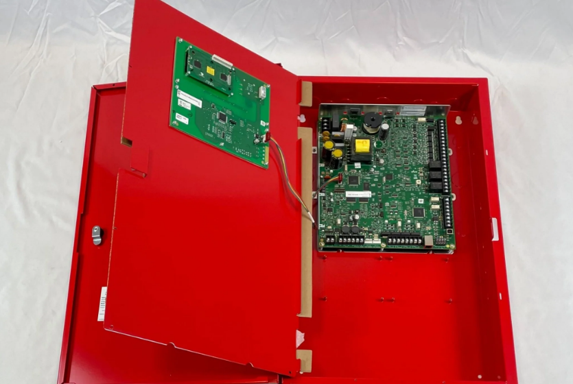
- main circuit board with the display
- backbox with door
- plastic bag containing two keys, screws, cables, and ten 4.7K ohm end-of-line resistors
- manual
Environmental Specifications
It is important to protect the 6700 control panel from water. To prevent water damage, the following precautions should be FOLLOWED when you install the units:
- Intended for indoor use in dry locations only.
- Do not mount the panel directly on exterior walls, especially masonry walls (condensation).
- Do not mount the panel directly on exterior walls below grade (condensation).
- Protect the panel from plumbing leaks.
- Protect the panel from splashes caused by Sprinkler System inspection ports.
- Do not mount the panel in areas with humidity-generating equipment (such as dryers, production machinery).
When you select a location to mount the 6700 control panel, the unit should be mounted where it will NOT be exposed to temperatures outside the range of 32°F-120°F (0°C-49°C) or humidity outside the range of 10%-93% at 86°F (30°C) non-condensing.
Software Downloads
In order to supply the latest features and functionality in fire alarm and life safety technology to our customers, we make frequent upgrades to the embedded software in our products. To ensure that you install and program the latest features, we strongly recommend that you download the most current version of the software for each product prior to commissioning any System. Contact Technical Support with any questions about software and the appropriate version for a specific application. The HFSS Honeywell Fire Software Suite is available at www.silentknight.com.
Electrical Specifications
Table 3.1 lists the terminal block on the 6700 as well as a description of each terminal and its respective electrical rating. For the location of the terminals, refer to Figure 4.3. See also Section 4 for installation information.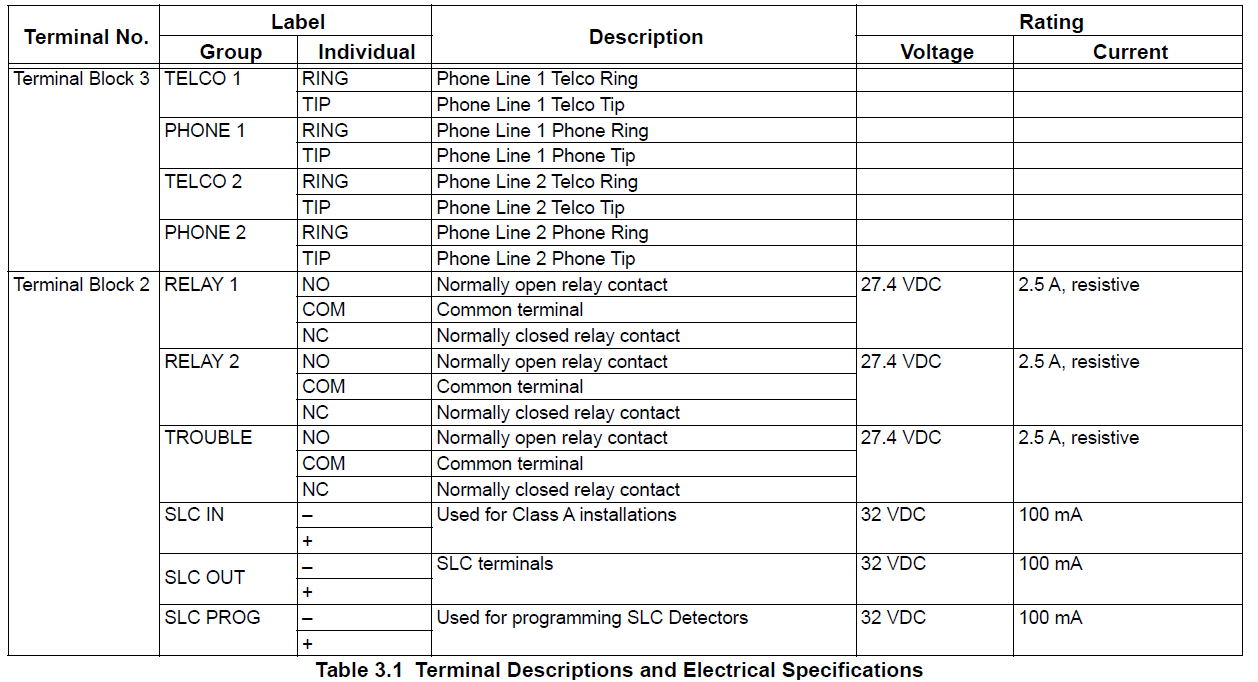

Calculating Current Draw and Standby Battery
This section contains instructions and tables for calculating current draws and standby battery needs.
Worksheet Requirements
The following steps must be taken when determining the 6700 current draw and standby battery requirements. Filling in the Current Draw Worksheet, or Table 3.3
- For the 6700, the worst-case current draw is listed for the panel, addressable devices, and SLC expanders. Fill in the number of addressable devices and expanders that will be used in the system and compute the current draw requirements for alarm and standby.
- Add up the current draw for all auxiliary devices and record in the table at Line B.
- Add up all notification appliance loads and record in the table at Line C.
- For notification appliances and auxiliary devices not mentioned in the manual, refer to the device manual for the current ratings.
- Make sure that the total alarm current calculated, including current for the panel itself, does not exceed 2.5 A. This is the maximum alarm current allowable. If the current is above 2.5A, you will need to use a notification power expander(s) such as, the 5496 NAC Expander. Use the expander(s) to distribute the power loads, so that the 6700 or the power expanders do not exceed their power rating. Refer to the Current Draw Worksheets provided with the 5496 Manual to identify the ratings that do not exceed their power requirements.
- Complete the remaining instructions in the table for determining battery size requirements.
Control Panel Installation
Mounting the Control Panel Cabinet
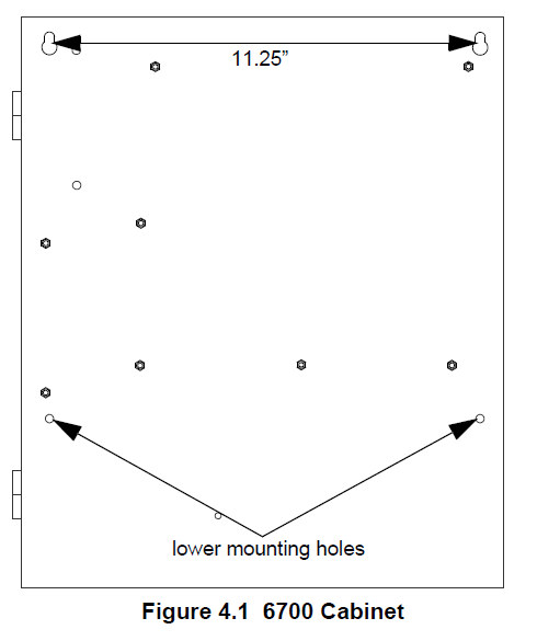
Read the Environmental Specifications in Section 3.2 before mounting the 6700 panel. The 6700 cabinet base dimensions are: 12.531” W x 14.875” H. The 6700 panel should be located within a secured area, where it is accessible to the main drop wiring runs and where it can be easily tested and serviced. End-users responsible for maintaining the panel should be able to hear alarms and troubles. When you select a location, keep in mind that the panel itself is the main source of alarm and trouble annunciation. When mounting on interior walls, use appropriate screw anchors in plaster. When mounting on concrete, especially when moisture is expected, attach a piece of ¾” plywood to the concrete surface and then attach the 6700 to the plywood. Also, mount any other desired components to the plywood. DO NOT flush-mount the 6700 cabinet in a wall designated as a fire break.
- Mark and pre-drill a hole in the wall for the top keyhole mounting bolt using the dimensions illustrated below.
- Install top fasteners in the wall with the screw head protruding.
- Place backbox over the top screws, level and secure.
- Mark and drill the left and right lower mounting holes.
- Install the remaining fasteners and tighten.

Preventing Water Damage
Water damage to the fire system can be caused by moisture entering the cabinet through the conduits. Conduits that are installed to enter the top of the cabinet are most likely to cause water problems. Installers should take reasonable precautions to prevent water from entering the cabinet. Water damage is not covered under the Warranty.
Removing the 6700 Assembly from the Housing
If it should ever be necessary to remove the control panel assembly from the cabinet for repair, do so by removing the screws that hold the control panel in to the cabinet. Do not attempt to disassemble the circuit boards.
Dead Front Installation and Removal
This section provides instructions to install and or remove the optional dead front for the control panel cabinet.
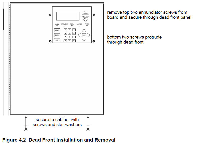
Installing the Dead Front. Follow these steps to properly install the dead front panel into the control panel cabinet.
- Remove the top two screws which secure the annunciator to the board. Leave the bottom two screws installed. See Figure 4.2 for annunciator screw location.
- Set the dead front into the cabinet.
- Close the dead front panel. The bottom two screws on the annunciator will protrude through the dead front panel.
- Reinstall the top two annunciator screws removed in step 1.
- Insert the two screws with the star washers into the bottom of the cabinet to secure the dead front to the cabinet.

Dead Front Removal
Follow these steps to properly remove the dead front panel from the control panel cabinet.
- Remove the top two annunciator screws. See Figure 4.2 for location.
- Remove the two screws and star washers from the bottom of the cabinet.
- Remove the dead front panel from the control panel cabinet.
- Reinstall the top two annunciator screws to secure to the board.
Common Communication Link
Hardware Features
Panels
The 6700 panel can be connected to other 6700 and addressable panels to create a link where one panel is designated as the communicator for all the panels in the link. Up to 17 panels can be connected in the Common Communication Link. This does not create a peer-to-peer network and will not operate as one.SK
Wiring Options to Connect Panels
The 6700 and other applicable addressable panels can be linked together for common communications to the central station. “Sites” are used to allow for individual or common announcements across the link. Up to 17 sites can be activated and programmed for the link.
- Fiber-Optic Single Mode – Use the SK-NIC and SK-FSL for up to 30dB loss of signal separation. SK-FSL connects to the link. using 9/125 micron single-mode fiber.
2. Fiber-Optic Multi-Mode – Use the SK-NIC and SK-FM for up to 8dB loss of signal separation SK- FML connects to the link using 62.5/125 micron multi-mode fiber. - Twisted-Pair Copper Wire – must use the SK-NIC to provide up to 3,000 feet of separation. All methods of panel connectivity can be used within the same linked system.
Direct Connect Wiring Option
When linking in a group of 6700 panels, you must use the SK-NIC to link the panels together. See Figure 5.1 for external mounting of SKNIC option.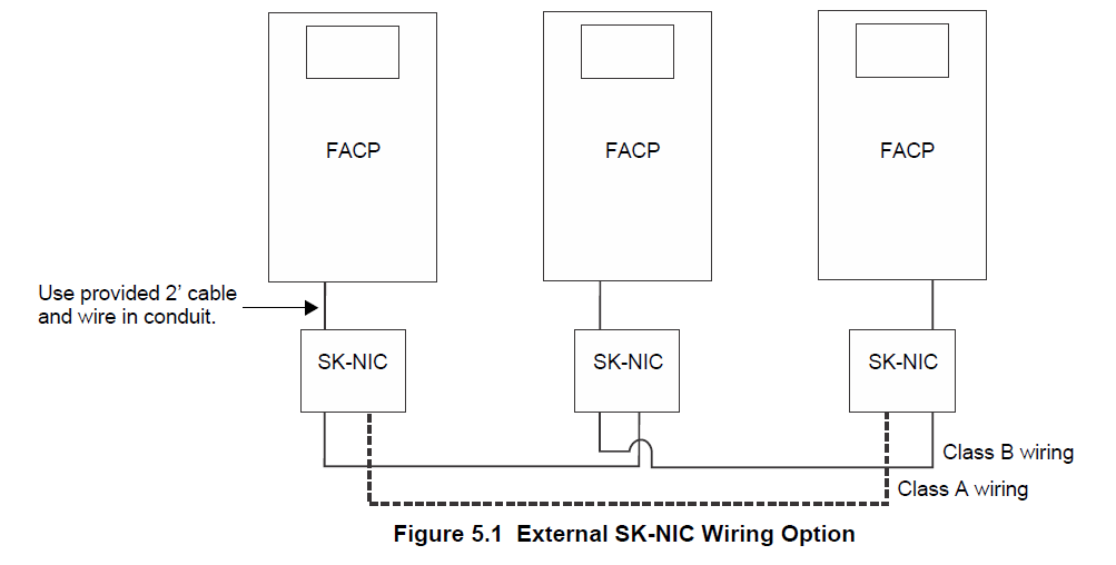
SK-NIC Wiring Options
Linking a group of6700 panels requires the use of a network interface card with each panel. The SK-NIC connects to other linked units using unshielded, twisted-pair wiring or fiber-optic cable.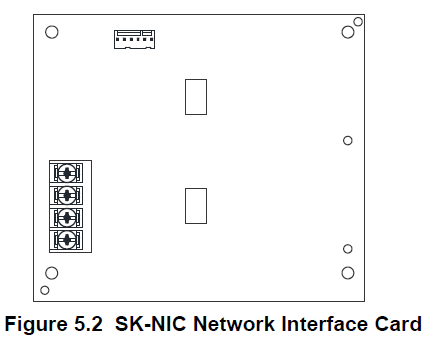
Fiber Loop Modules
Two types of fiber-optic modules are available to use to transmit and receive communication with the SK-NIC.
The SK-FML (Fiber-Optic Multi-Mode) and SK-FSL (Fiber-Optic Single-Mode) are plug-in fiber loop modules. The two types of fiber-optic modules are used as one channel to transmit or receive communications with the SK-NIC, ARCNET communication circuit. The following describes the two types of fiber-optic modules.
- The SK-FML is a fiber module that allows the multi-mode fiber to link between nodes.
- The SK-FSL is a fiber module that allows a single-mode fiber to link between nodes.
Each fiber loop module can transmit (TX) and receive (RX) fiber-optic cable connecting to the SK-NIC. Up to two fiber loop cards can be added to the SK-NIC, and both cards may be combined in the same configuration. See Figure 5.4.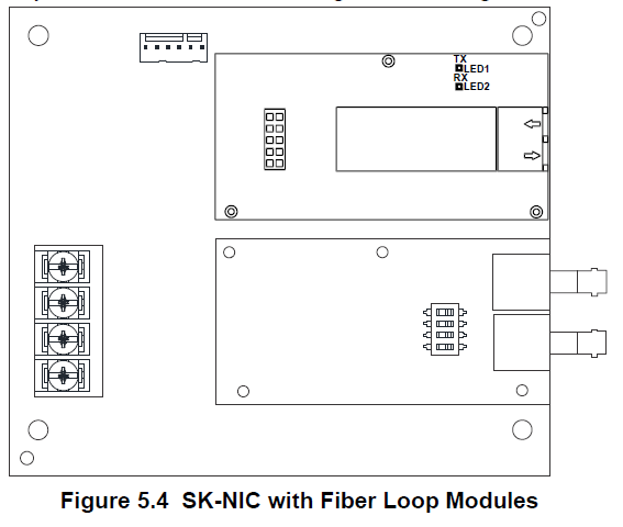
SK-NIC Mounting Kits
SK-NIC can be mounted in an accessory cabinet. An accessory kit is necessary to install the SK-NIC outside of the 6700 cabinet.
- The SK-NIC-KIT includes a SK-NIC, a small cabinet with a locking door, cable, and mounting hardware.
- The 5815RMK includes a small cabinet with a locking door and mounting hardware.
Network Management
Network Diagnostics
Ping Panel
The Ping Panel Menu allows you to continually ping any panel programmed into the network. As the selected panel is being pinged, the Ping Panel screen will display the reply time, minimum, maximum reply times, and sent and received counters.
- Log in to the panel. The panel will automatically access the Main Menu.
- Select 5 to access the Network Diagnostics.
- Press 1 to enter the Ping Panel Menu.
- Press the up or down arrow key to select the Network Panel ID. Press ENTER to Ping the panel.
Data Network Status
The Data Network Status screen will display statistics that are indicators of the network’s performance.
- Log in to the panel. The panel will automatically access the Main Menu.
- Select 5 to access the Network Diagnostics.
- Press 2 to enter the Data Network Status Menu.
Network Programming
This section of the manual describes how to program the network options using the built-in annunciator. All options described in this section can be programmed using the HFSS Honeywell Fire Software Suite. HFSS must be used to edit site assignments.
Learn Network
The Learn Network Menu displays all of the panels connected to the network. Any panel that has been programmed into the network will appear as a “member.” Any panel that is connected to the network, but not programmed into the network will appear as a “guest.” In this Menu, you can add the guest panels to the network by changing their status to member panels. Panels showing OK are currently responding on the network. Panels not showing OK were either removed or are not responding due to the networking problems. See Section 6.1 above for Network Diagnostics.
- Log in to the panel. The panel will automatically access the Main Menu.
- Select 6 to access the Network Programming.
- Press 1 to enter the Learn Network Menu.
- Press ENTER to add or remove the panels (identified as either a member or a guest) connected to the network.
Incompatible Panel
If you try to add an incompatible panel as a member to the network, the Learn Network fails, and an error message appears. The incompatible panel remains a “guest”. To continue, remove the incompatible panel from the network.
Edit Network Names
The Edit Network Menu allows you to edit the panel name and the panel’s site name.
Edit Panel Names
- Log in to the panel. The panel will automatically access the Main Menu.
- Select 6 to access the Network Programming.
- Press 2 to enter the Edit Network Names Menu.
- Press 1 to select Edit Panel Name. Choose the panel to edit.
Edit Site Names - Press 2 to select Edit Site Name. Choose the site to edit.
See Appendix A for a list of available characters and their numeric designators.
Edit Panel ID
This Menu option allows you to change the current Network Panel ID. It is best to carefully consider the network ID setting for each panel. Take into account any future panels that will be added to the network (for example, future wiring of two buildings together). The Network Panel ID setting must be assigned a unique ID for each panel on the network. This Menu will allow you to change the currently assigned Network Panel ID to the current Network ID DIP switch setting. The System will be down as the panel needs to reboot in order to complete the transition. When you use HFSS to program the panels, the Network Panel ID will be locked from future editing. The only way to change the Network Panel ID is to restore the defaults and use this Menu again.
Edit the Network Panel ID
- Log in to the panel. The panel will automatically access the Main Menu.
- Select 6 to access Network programming.
- Press 3 to enter the Edit Panel ID Menu.
- If the Network Panel ID is changed and valid, the system will ask you to confirm the change. If it is not correct, you can change the DIP switches at this time.
- Press the up arrow key to select YES and press ENTER to confirm.
Testing and Troubleshooting
Troubleshooting
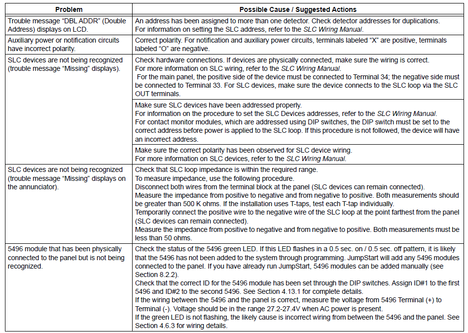
This section of the manual offers suggestions for troubleshooting hardware problems. Please read this section if you encounter a problem when you install the fire alarm control panel. If these suggestions do not solve your problem or if you encounter a problem that is not listed, contact Silent Knight technical support for assistance.
Troubleshooting Common Problems
Periodic Testing And Maintenance
To ensure proper and reliable operation, it is recommended that the System inspection and testing be scheduled monthly or as required by the national and/or local fire codes. Testing should be done by a qualified services representative if a malfunction is encountered. Before testing:
- Notify the fire department and/or the Central Alarm Receiving Station if an alarm condition is transmitted.
- Notify the facility personnel of a test so that the alarm-sounding devices are ignored during the test period.
- When necessary, activation of notification appliances can be prevented by the DISABLE function.
Testing:
- Activate an input via an alarm-initiating device and check that the correct outputs activate (notification appliances sound/flash, relays activate, alarm LED lights). Reset the system. Repeat for each alarm-initiating device.
- Momentarily open the following circuits one at a time and check for a trouble signal:
- notification appliance (bell) circuits
- initiating devices
- If new batteries were installed, wait 48 hours before completing this step. Remove the AC power, activate the initiating device, and check that the following occurs:
- The ALARM indicator lights.
- All active notification appliances sound.
Measure the battery voltage while the notification appliances are sounding. Replace any battery with a terminal voltage less than 85% of the rating. Reapply the AC power and reset the system.
Event History
The event history can be useful for tracking or recalling a trouble condition.
To view event history:
- Log in to the panel.
- Press 3 to select Event History.
- Press the up or down arrow key to view events in the history buffer.
For more manuals by Honeywell, visit ManualsLibraryy
Honeywell 6700 Silent Knight Fire Alarm Control Panel-FAQs
What is the Honeywell 6700 fire alarm control panel?
The 6700 is an addressable fire alarm control panel (FACP) that supports up to 100 addressable points. It includes one built-in signaling line circuit (SLC) that can support 50 System Sensor SK sensors and 50 SK modules or 50 Hochiki SD devices.
How many addressable points can the 6700 support with SD devices?
When using Hochiki SD addressable devices, the 6700 panel supports up to 100 total points.
How does a fire alarm control panel work?
The panel monitors connected input devices like smoke detectors or manual call points. When a fire is detected, it activates alarms and notifies other systems, including remote monitoring centers, if networked.
What is the default master code for Honeywell panels?
The default Master Code is 1234 and the Installer Code is 4112. For security reasons, it’s advised to change the Master Code after setup.
Is System Sensor a Honeywell brand?
Yes, System Sensor is part of Honeywell, a global leader in commercial fire detection technology.
What is the installer code for the Silent Knight 6820 panel?
The default Installer Code is typically 123456, but this may vary depending on the setup or local programming.
How many points can the IFP-2100 support using SD addressable devices?
The IFP-2100 supports up to 2,100 addressable points. Each SLC loop can handle 127 Hochiki SD devices, or 159 IDP/SK sensors and 159 modules.
How do I silence the Honeywell fire alarm panel?
To silence an active alarm, press the “Fire Alarm Silence” button on the control panel. This stops the local sounders after a detector has been triggered.

