
Korg M1R Rackmount Workstation Synthesizer

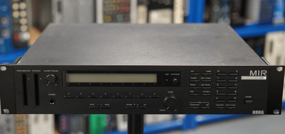
FRONT/REAR PANELS
FRONT PANEL
(See the KEYS AND CONTROLS section, p.9, for explanations on each key and control.)
- PROG/SEQ DATA slot
Only cards that are stored or will be stored with the Program (sound color) and sequencer data should be inserted here. Remember that the PCM (Multisound) data card should be inserted in the PCM data slot on the front panel. - PCM DATA slot
Only cards that are stored with PCM (Muilisound) data should be inserted here. Do not insert the Program/sequence data cards here. - MASTER VOLUME
- PHONES jack
For connection of a stereo headphone set. The outputs of OUTPUT I/LL and 2/R can be monitored. - Display
- MIDI indicator
This lights up when MIDI signals are being received. - CONTRAST dial
This controls the brightness of the display on the front panel. Turning the dial clockwise darkens the characters on the display and turning it counterclockwise lightens them. - Cursor keys (A-H)
- PAGE +/- keys
- UP
 /DOWN
/DOWN keys
keys - VALUE Dial
- INT key/CARD key
- Mode Select keys
- COMBI = COMBINATION Mode
- EDIT COMBI = EDIT COMBINATION Mode
- PROG = PROGRAM Mode
- EDIT PROG = EDIT PROGRAM Mode
- SEQ = SEQUENCER Mode
- GLOBAL = GLOBAL Mode
- START/STOP keys
- REC key
- Numeric keypad (0-9)
- COMPARE key
- BANK HOLD key
REAR PANEL

- MIDI THRU jack
- MIDI OUT jack
- MIDI IN jack
- ASS. PEDAL/SW jacks (1,2)
For connection of pedal and footswitches, assigning the switches control parameters 10 is done in the eile): 0 4A Mode, Function F 2-1. - OUTPUT jacks (1/L, 2/R, 3, 4)
These are the MIR’s voice output jacks. The assignment of voices to the desired jacks is done in each of the Effect Parameters sections of the EDIT PROGRAM, EDIT COMBINATION, and SEQUENCER Modes.
BASIC OPERATION
STRUCTURE OF THE MJR
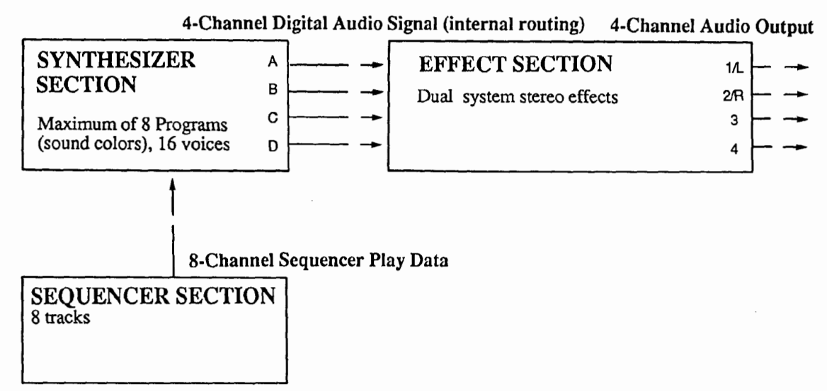
AI SYNTHESIS SYSTEM
The AI (Advanced Integrated) synthesis system of the MIR makes it possible to combine all various sound types from conventional synthesizer sounds to sampled sounds and drum sounds. For sampled sounds, the large-capacity PCM data memory of 16-bit x 2 megabytes, far greater than that of conventional samplers, has been utilized, and a carefully selected group of Multisounds (a sound whose original wave shape has been multi-sampled) has been installed. For its synthesizer sounds, not only the D.W.G.S. waveforms, which are produced by a process much the same as that of an analog synthesizer, but also aperiodic or irregular waveforms created by extraction of harmonically unrelated frequency components, are part of the MIR’s structure. As a result, the creation of new and unique sounds beyond the existing limitations of the conventional synthesizer is possible. Processing any of the programs or individual sounds with the use of VDFs (Variable Digital Filter) and VDAs (Variable Digital Amplifier) is, of course, possible. Moreover, different effects can be assigned to specific programs in a configuration of 2 systems and 2 channels through the M1R’s MDE (Multi Digital Effect) feature when playing Multisounds. With the use of these functions, total control over all aspects of sound creation, including effects, is possible.
Multi Sampling
The harmonic structure and overtones present in high-pitched sounds usually differ from those of low-pitched sounds, even in the same musical instrument. Multi-sampling is a method to recreate those characteristics by sampling an instrument repeatedly over a range of many octaves.
D, W.G.S. (Digital Waveform Generator System) Waveform Data
The instrument sound is reproduced by the following process: Computer analysis determines the frequency components of the sampled instrument sound and reproduces them by creating a harmonic table for them, as is done in additive synthesis.
Extraction of Harmlessly Unrelated Frequency Components
Separates the aperiodic and harmonically unrelated components characteristic of such sounds as objects being hit or scraped from the sampled wave shapes.
MULTISOUND
(Original Sound Waveforms)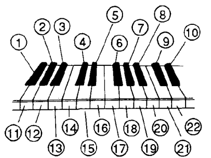
The oscillator (OSC) is selected from the Multisound (00 to 99).
- Multisounds can be selected from the PCM card.
- See EDIT PROGRAM mode, F0-2 for more details.
An original program can be created by performing various processes to the Multisound.
- The VDF (Variable Digital Filter) controls the sound color.
- The VDA (Variable Digital Amplifier) controls the sound volume.
- These processes are done in the EDIT PROGRAM Mode.
INSTRUMENT SETTINGS DRUM KIT
Assigns drum sounds to the keys.
Example:
- BASSDRUM 1
- SNARE1
- HITOM
- CLOSED HIHAT
- OPENHIHAT
- CRASH CYMBAL 1
- RIDECYMBAL 1
- HAND CLAPS
- HICONGA (MUTED)
- LO BONGO
- BASS DRUM2
- SNARE2
- MID TOM
- LOTOM
- CLOSED HIHAT
- PICCOLO SNARE 1
- PICCOLO SNARE 2
- CRASH CYMBAL 2
- RIDECYMBAL 2
- HICONGA (OPEN)
- LOCONGA (MUTED)
- HIBONGOInstrument settings, including pan, are edited in the GLOBAL Mode.
PROGRAM MODE
- The work “Program” as referred to in this manual is synonymous with “sound color” or “preset voice” in other synthesizers.
- Program numbers available for selection are from 00 to 99. (Selection from only 00 to 49 is possible when a large sequence allocation is selected.)

- The EDIT PROGRAM Mode Single can be used for making settings up to this point.
- Choose from 4 different instrument settings.
- The pan setting of the Drum Kit, which is set in the GLOBAL Mode, has priority.
COMBINATION MODE
- The word “Combination” as referred to in this manual means two or more programs that have been grouped for simultaneous play.
- Combination numbers available for selection are from 00 to 99. (Selection from only 00 to 49 is possible when a large sequence allocation is selected.)
- Program changes received via MIDI in the COMBINATION Mode change the Combination.

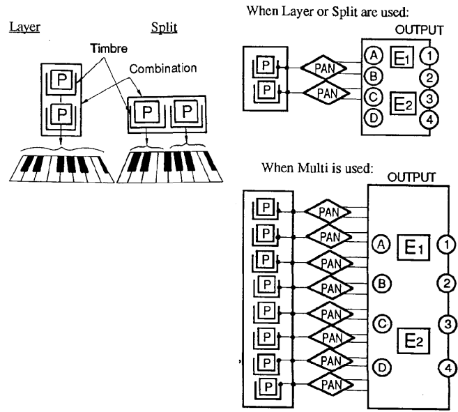
Settings for Layer or Split can be made in the EDIT COMBINATION Mode. Separate MIDI channels can be assigned to each Program (or timbre) when Multi is chosen. In this way, one MlR Music Workstation can, with the aid of an external sequencer, output eight different sound colors at the same time. When using the MLR’s built-in sequencer, Programs can be assigned to each track of the sequencer without having to create a Combination.
SEQUENCER MODE (Song to 9)
When using external sound sources: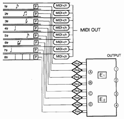
- Programs are assigned to each song.
- The pan setting can be made for each track.
- The effect setting can be made for each song.
- 1 song can be made up of 8 tracks
- Tracks cq11 be created by combining patterns (00 to 99).
PAN
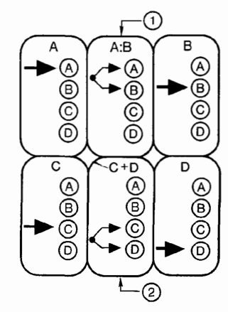
- The volume difference between the two outputs can be changed over a range of ratios from 1:9 ∼ 9:1.
- Sends signals to C and D at the same volume.
EFFECT E1, E2
When set to parallel operation: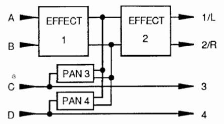
When set to serial operation: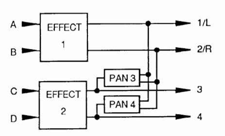
Effect1 and Effect2 are set in the effects pages of each mode.
KEYS AND CONTROLS
Numeric Keypad
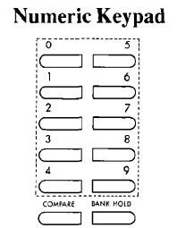
These are used to:
- Select the Combination in the COMBINATION Mode.
- Select functions in other modes.
BANK HOLD Key
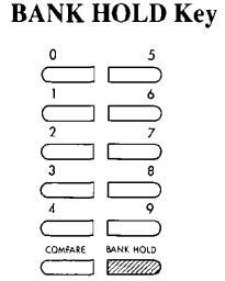
The tens digit of the program or combination number can be “held” while changing program or combination numbers by using the BANK HOLD key. For example, pressing the BANK HOLD key once after number 21 has been selected will allow you to select other numbers in the 20-29 range simply by pressing the number that corresponds to the ones digit of the desired number; in our example, pressing 3 will change the number to 23, pressing to 7 will change it to 27, and so on. The BANK HOLD key will be lit when the Bank Hold function is on. To turn the function off, press the BANK HOLD key once more.
EDIT PROGRAM MODE
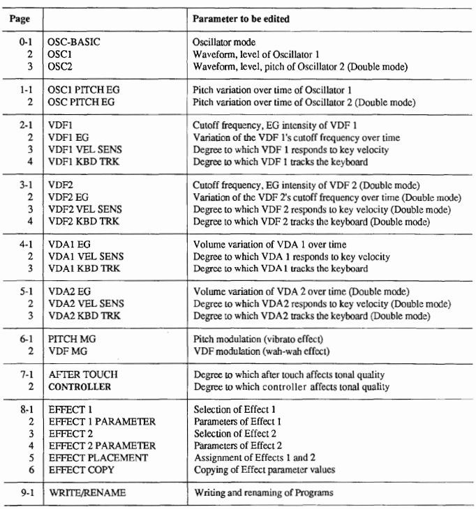
In this mode, the Program parameters (such as original waveform settings and filter EG values, etc.) are set.
- Only the Programs that have already been selected in the PROGRAM Mode can be edited.
- Editing in real time (for changing parameters in live performance) can be done in the PROGRAM Mode.
- Use the F9-1 Write Program function after finishing any edits, and the Program will be completed. (Programs which are not written to memory are irretrievably lost when selecting other programs in the PROGRAM Mode.)
- Pressing the COMPARE key during editing can recall the original, un-edited program for comparison.
- Pressing the COMPARE key again and leaving the Program without editing it returns you to the Program which was being edited before the COMPARE key was pressed.
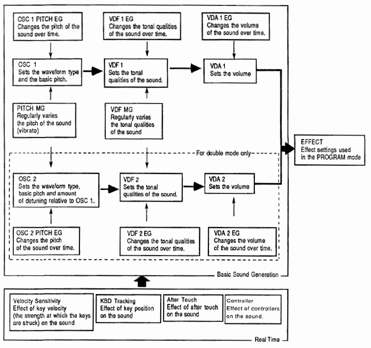
STRUCTURE OF THE ML’S PROGRAM PARAMETERS
FUNCTIONS IN THE EDIT PROGRAM MODE
- The first page of each function is selected by pressing the numeric keypad (0 to 9). Select the page on which the parameter you want to edit shows using the PAGE+ key and PAGE – key.
- The maximum pitch change of the various pitch controls, such as pitch bend, pitch EG, pitch modulation, and after touch, is limited to one octave. (Some Multisounds have an even smaller range, depending on the actual pitch range of the sound .)
- VDF and VDF EG parameters as well as the change in timbre by VDF MG, are limited to the total controllable range of the VDF.
- Oscillator level and VDA parameters, as well as volume change by VOA EG, are limited to the total controllable range of the VDA.

EDITING IN THE EDIT PROGRAM MODE
F O – 1 OSC BASIC (Oscillator)
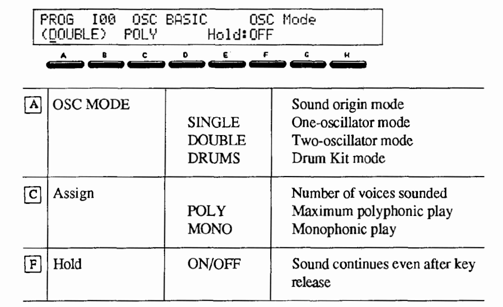
In the OSC MODE (oscillator mode), the structure of the Program to be made is selected. The oscillator number and the type of sound origin will change according to the settings made here.
- When switching the OSC MODE, reset the multisound (Drum Kit) of OSC I on the following page.
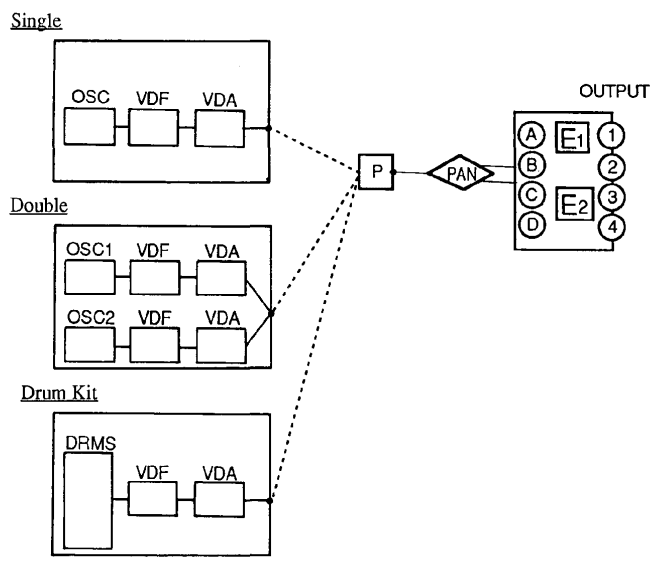
- In SINGLE, a one-system OSC/VDF/VDA is used. The maximum simultaneous voices available are 16.
- In DOUBLE, two OSC/VDF/VDA systems are used. Sounds of greater complexity can be created here, but the maximum simultaneous voices available are decreased to 8.
- DRUM KIT is a mode that uses drum sounds as the sound origin to make up a keyboard-controllable drum kit.
Assign determines whether the program is to be played polyphonically or monophonically. When the Hold parameter is set to ON, notes played will continue to sound even after releasing the key. This is used mainly for playing the Drum Kit.
- The sound will not stop but will continue for the full duration of the sustain parameter when Hold is set to ON.
F O – 2 OSCl (Oscillator 1)
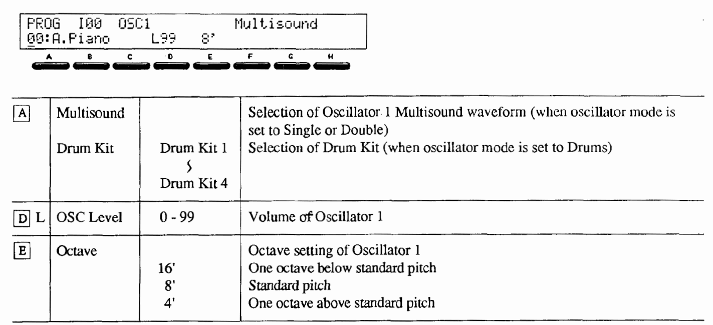
When SINGLE or DOUBLE is selected in function F O – 1, OSC MODE, the waveform of Oscillator I is selected by Multis.ound (Multisound Select). (A list of the Multisounds is on the back cover.)
- Since each Multisound (sound origin waveform) has a limited pitch range, it may not sound when playing in a high octave.
- Multisounds can be chosen from CARD if the PCM card (optional) is inserted in the rear panel. Multisounds within the CARD are indicated by a “C” in front of the number on the display and can be seen in succession by moving the VALUE slider up and down.
NOTE: Make sure to insert or take out the PCM card only when the power is OFF or when no sound comes from the M1 R.
Selects one of the Drum Kits (1 to 4), when DRUM KIT is selected in the OSC MODE.
- Assignment of drum sounds to the Drum Kit is done in GLOBAL Mode.
OSC Level (oscillator level) sets the sound volume of Oscillator I. The maximum is 99 and the minimum is 0. Octave sets the basic pitch of Oscillator l in octave units.
EFFECT PARAMETERS
A two-system, two-channel Multi Digital Effect unit is built into the MlR. Each effect has a wide range of effect types that can be selected, such as reverb, delay, chorus, flanger, phase shifter, distortion and exciter, and fine adjustment of all effect parameters is possible. Since all effects can be assigned separately to each Program, Combination and song track, you can use the most appropriate effect for each and every playing situation.
- The Effect functions can be considered together as an additional element in the sound-making process since effect settings can be changed for each Program.
- Assigning different effects to specific Programs is possible when using Drum Kit Programs, Combinations and the sequencer.
Editing of the effect parameters is executed in the Edit Program Mode, Edit Combination Mode or Sequencer Mode. (Details of editing and parameters are identical.) The Effect section is comprised of 2 effects and 2 panpots with a 4-input (A, B, C, and D) and 4-output (1/L, 2/R, 3, and 4) configuration. For the placement of the 2 effects, there are 2 operation modes: serial and parallel. (All signal routing is digital; the signal is changed from digital to audio with the D/A converter only after passing through the Effect section.)
EFFECT PLACEMENT
Serial Routing
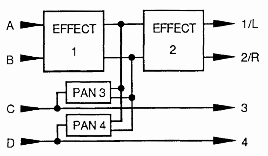
Inputs A and B send signals to both Effect I and Effect 2 and are output from 1/L and 2/R. Signals from C and D are output through 3 and 4 unprocessed. The output signals from 3 and 4 can also be mixed with the A and B inputs to be routed together through Effect 2.
- Selected Programs can be processed through Effect I and other Programs not, while all Programs -processed or not — can be routed through Effect 2; this kind of setting is possible by using the C and D inputs.
Parallel Routing
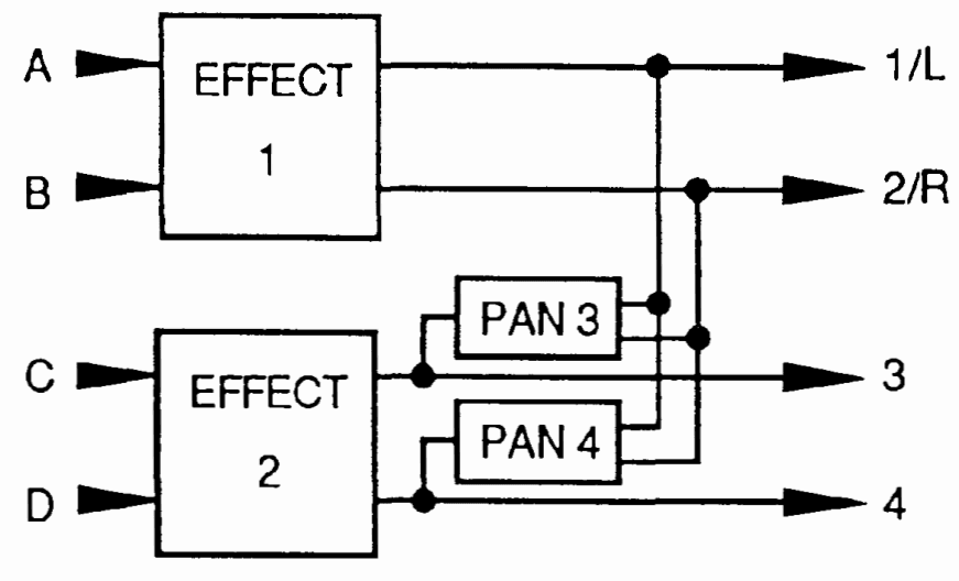
Different effects are used for each input pair, inputs A and B, and inputs C and D, and each of them are sent directly to outputs 1/L, 2/R, 3, and 4. The outputs from 3 and 4 can be mixed with the Effect 1 outputs and sent through the outputs 1/L and 2/R.
- There are two types of effects: effects 1 – 25 are stereo effects, and 26 – 33 are dual effects in which each channel has a different effect.
- Signal routing for inputs A through Disis is set by using the panpot functions in the Combination parameter in the COMBINATION Mode and the Track parameter in the SEQUENCER Mode. Instrument Pan (Global F 4) is available for Programs of the drum kit programs. Programs except drum kit, are input to A and B in a ratio of 5:5 and not input to C and D.
- The following various settings are possible by setting the pans of each Program by using Output 3 Pan and Output 4 Pan.
- Different sounds that are output to C and D can be mixed with the stereo output by adjusting the pan setting of each Program with Output 3 Pan and Output 4 Pan.
- When stereo effects have been selected for Effect 1 and 2, and the operation mode has been set to Parallel, stereo out mixed outputs of Effect 1 and Effect 2 can be used by setting Output 3 Pan to 100:0, and Output 4 Pan to 0: 100.
- When using an external effect or mixer, outputs 3 and 4 can be used as separate outputs by setting the Output 3 Pan and Output 4 Pan to OFF.
F 8 – 1 EFFECT 1
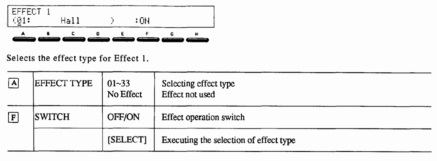
- [SELECT] is indicated on the display when the EFFECT TYPE is changed.
- Select the EFFECT TYPE [A] and press [SELECT] [E]; the effect type selected will now be in operation. (The selection is· cancelled when selecting other effect types instead of pressing [SELECT].)
- When selecting the effect type again, effect parameters will be set to the default value (see pp.56-57).
- Note that among the 2-system effects, when #24 Symphonic Ensemble and #25 Rotary Speaker are both selected for one system, the Effect types which are marked with an asterisk on the following chart cannot be selected for the second effect. (Likewise, when an asterisk-indicated Effect type is selected for one system, #24 and #25 cannot be selected for the other. Refer to the Effect Parameter Default Values Chart, pp.56-57, for more information.)
- See explanations about each effect type for details.
- When assigning the footswitch to Effect in GLOBAL Mode F 2 – 2, Pedal Assign, the effect is toggled ON and OFF each time the footswitch is pressed.
Switch ( [F] ) indicates and sets the condition of the switch. - When selecting another Program, Combination, or song, the ON/OFF setting returns to the condition set in the effect parameter of each mode.
- For all effects except Reverb (01 to 06), Overdrive (21), Distortion (22), and Ensemble (24) , the equalizer settings (Low EQ and High EQ) are effective even when the effect switch is OFF.
Set the effect type to No Effect when you want all effects, including the equalizer, to be off while editing Programs.
F 8 – 2 EFFECT 1 PARAMETER
Sets the parameter of Effect 1.
- See explanations about each parameter type (starting on p. 40) since the details of the parameters differ depending on the parameter type.
- The value set here is lost when selecting another. Effect type for Effect 1.
F 8 – 3 EFFECT 2 Selects the effect type for Effect 2.
Same as F 8 – 1 EFFECT 1.
F 8 – 4 EFFECT 2 PARAMETER
Sets the parameters of Effect 2.
- See explanations about each parameter (starting on p. 40) type since the details of the parameters differ depending on the parameter type.
- The value set here is lost when selecting another ·effect type for Effect 2.
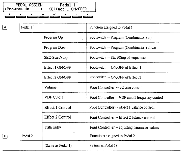
F 2 – 1 PEDAL ASSIGN
 Selects the function to be assigned to Pedal 1 and Pedal 2.
- Connect the footswitch or foot controller to the jack of Pedal l or 2, depending on the function to be selected.
- The range controllable by the foot controller may sometimes be limited by the corresponding parameter settings.
- Program Up: Switches to the next Program (or, in PROG/COMBI Mode, Combination) by footswitch. When this is selected, MIDI program change data is sent from MIDI OUT.
- Program Down: Selects the previous Program (or, in PROG/COMBI Mode, Combination) by footswitch.
- SEQ Start/Stop: Starts and stops the sequencer by footswitch.
- Effect I ON/OFF: Toggles Effect I on and off by footswitch.
- Effect 2 ON/OFF: Toggles Effect 2 on and off by footswitch.
- Volume: Controls the volume of MlR by foot controller.
- VDF Cutoff: Changes the cutoff frequency by foot controller. The cutoff frequency is raised by pressing down the pedal. (The sound color becomes brighter.)
- Effect I Balance: Determines the overall balance between the direct sound and the effect sound of
- Effect I by foot controller. The ratio of the effect sound to direct sound becomes greater when pressing down the pedal.
- Effect 2 Balance: Determines the overall balance between the direct sound and the effect sound of
- Effect 2 by foot controller. The ratio of the effect sound to direct sound becomes greater when pressing down the pedal.
- Data Entry: Allows changing and adjustment of parameter values (usually controlled by the VALUE dial on the panel) by using the foot controller. The value of each parameter can be controlled by the foot controller while playing if the parameters to be changed are selected beforehand.
- Make sure to match the footswitch/foot controller connection to the assigned functions.
- We recommend using the KORG EXP-2 for the foot controller.
NOTE: When no pedals or footswitches are connected to the rear panel jacks, set this function’s parameters to correspond to footswitch operation functions (Program Up, Program Down, SEQ Start/Stop, Effect ON/OFF).
SPECIFICATIONS AND MISCELLANEOUS INFORMATION
SPECIFICATIONS
- Sound generation method: Al Synthesis system (full digital sound processing)
- Sound source: 16 voice, 16 oscillator (Single mode) 8 voice, 16 oscillator (Double mode)
- Waveform memory: PCM; 2 Mword (4 Mbyte)
- Quantization: 16-bit
- Effect section: 2-system digital multi-effects
- Program memory capacity: 100 Programs iL
- Combination memory capacity: 100 Combinations
- Sequencer section: 10 songs, 100 patterns, max. 7700 notes RZ 8 tracks, 8-timbre multi-timbral operation (Dynamic Voice Allocation)
- Controller inputs: Damper pedal, assignable footswitches (pedals) 1/2
- Outputs: 1/L, 2/R, 3, 4, stereo headphones
- MIDI terminals: IN, OUT, THRU
- Display: Backlit LCD (40 characters x 2 lines)
- Optional accessories: RAM card (MCR-03), ROM card, PCM card
- Power requirements: nw
- Dimensions: 430 (W) x 405 (D) x 88 (H) (16 – 15/16″ x 15 – 15/16″ x 3 – 7/16″)
- Weight: 5.9kg (13 lbs.. 208 oz.)
* 1 Memory allocation can be changed to 50 Programs and 50 Combinations.
*2 A capacity of 4400 notes when the 100 Program/JOO _Combination memory allocation is selected.
* Specifications are subject to change and improvement without notice.
For more manuals by Korg, visit ManualsLibraryy
Korg M1R Rackmount Workstation Synthesizer-FAQs

 Selects the function to be assigned to Pedal 1 and Pedal 2.