
![]()
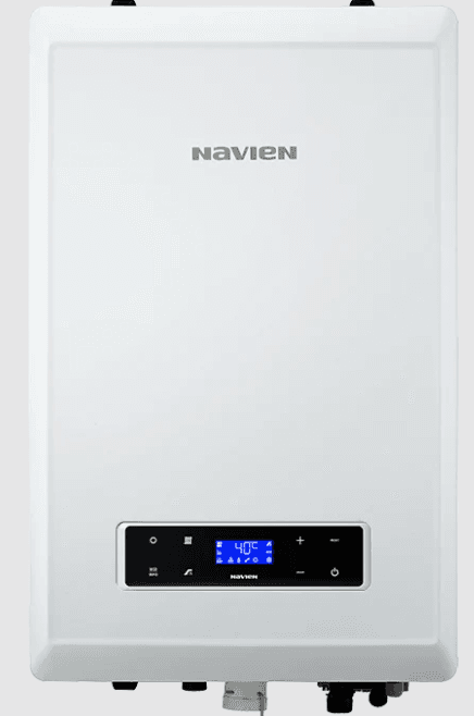
Navien NCB-150E Condensing Combi-Boilers
Safety Information
Safety Definitions
The following safety symbols are used in this manual. Read and follow all safety instructions in this manual precisely to avoid unsafe operating conditions, fire, explosion, property damage, personal injury, or death.
DANGER
HOT WATER TEMPERATURE SETTING
- Water temperatures at or above 125°F (52°C) can cause severe burns instantly or death from scalds.
- Households with small children, disabled, or elderly persons may require 120 °F (49°C) or a lower temperature setting to prevent contact with “HOT” water.
TO PREVENT BURNS
- Use the lowest operating temperature setting necessary to provide comfortably hot water.
- If your household has children or elderly or disabled residents, consider using a lower temperature setting.
- Read all the instructions in this manual carefully before changing the temperature setting.
- Feel the water before using it on children, the elderly, or the disabled.
- Contact a licensed plumber or your local plumbing authority for more information.
- This boiler’s water temperature is set to 120°F (49°C) at the factory for your safety and comfort. Increasing the temperature increases the risk of accidental scalding. Water temperatures at or above 125°F (52°C) can cause instant scalding, severe burns, or death. Before you decide to change the temperature setting, read the following charts carefully.
| Water Temperature | Time in which a young child can suffer a full thickness (3rd degree) burn |
| 160°F (70 °C) | Less than 1 second |
| 140°F (60 °C) | 1 second |
| 130°F (55 °C) | 10 second |
| 120°F (49 °C) | 10 minutes |
| 100°F (37 °C) | very low scald risk |
INSTALLATION REQUIREMENTS
- Installation conditions may affect how the boiler is serviced. Read all related information in the “Installation Manual”.
- The Boilers must be installed according to all local and state codes or, in the absence of local and state codes, the most recent edition of the “National Fuel Gas Code (ANSI Z223.1/NFPA 54)” in the USA or the “National Gas and Propane Installation Code (CAN/CSA B 149.1)” in Canada.
- Massachusetts code requires this boiler to be installed in accordance with Massachusetts Plumbing and Fuel Gas Code 248 CMR Section 2.00 and 5.00.
IMPORTANT SAFETY PREAUTIONS
- Read and understand this safety information before operating or servicing this Navien Boiler.
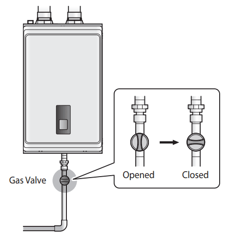
- Confirm the location of the gas shut-off valve. Close the manual shut-off valve if the Navien Boiler ever becomes subjected to overheating, fire, flood, physical damage or any other such damaging condition during servicing.
- DO NOT turn on the boiler unless water and gas supplies are fully opened.
- DO NOT turn on the boiler if the cold water supply shut-off valve is closed.
- Make certain power to the boiler is “OFF” before removing the front cover for any reason.
- Label all wires prior to disconnection when servicing controls. Wiring errors can cause improper and dangerous operations. Verify proper operation after servicing.
- Improper adjustment, alteration, service, or maintenance can cause property damage, personal injury, or death.
- To prevent scalding, always check the temperature of the hot water after servicing.
- DO NOT attempt to change the water temperature while someone is using the boiler.
- DO NOT use parts other than those specified for this equipment.
- DO NOT operate the boiler if you feel something is wrong with the unit.
- DO NOT allow children to operate or otherwise handle the unit.
Product Information
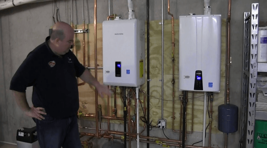
Navien features the NCB-E series gas boiler with a built-in Circulation Pump and Air vent. This appliance is fully modulated and provides central heating and domestic hot water. Depending on the heat capacity, each model is divided into three types; 150E, 210E and 240E.
| Model | Maximum Space Heating Input | Maximum DHW Input |
| NCB-150E | 60,000 BTU/H | 120,000 BTU/H |
| NCB-180E | 80,000 BTU/H | 150,000 BTU/H |
| NCB-210E | 100,000 BTU/H | 180,000 BTU/H |
| NCB-240E | 120,000 BTU/H | 199,900 BTU/H |
The appliance always gives priority to DHW supply. Navien features the NCB-E series boiler with a built-in Circulation pump and 3-way valve assembly, Flow sensor, DHW plate heat exchanger, and safety valve(or relief valve). A separate heating expansion vessel is required. Internal freeze protection and an electronic control unit are incorporated within the boiler. Any standalone room thermostat or set of contacts can be used with the boiler.
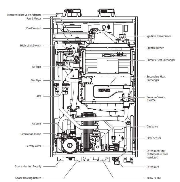
Components
The following diagram shows the key components of the boiler. Component assembly diagrams and particular parts lists are included in the Appendixes.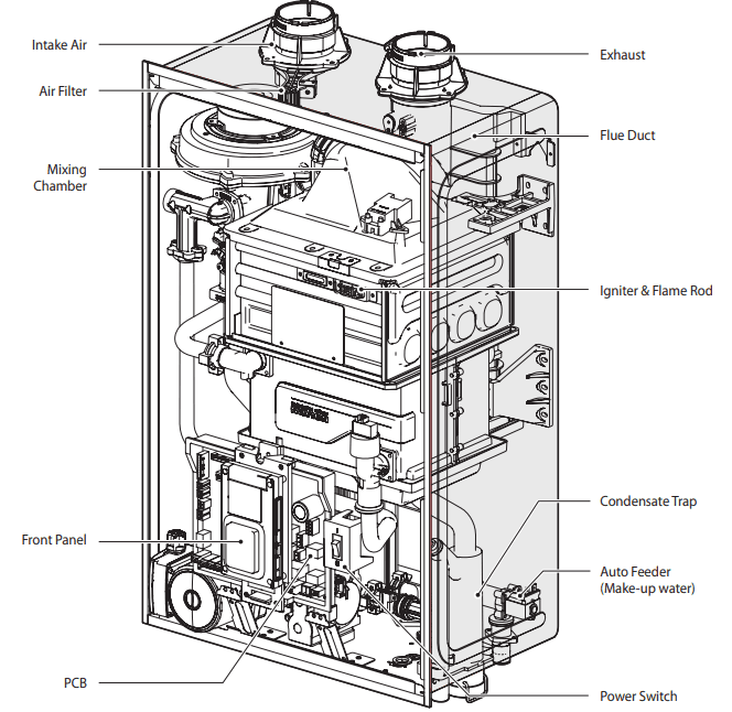
Technical Data
General Specifications
The following table lists the specifications for the boiler. Additional specifications about water, gas, electric, and air supplies (venting) appear in the Installation section.
Space Heating Specifications
| Navien Combination Boiler Space Heating Ratings | Other Specifications | ||||||
| Model Number1 | Heating Input, MBH | Heating Capacity2, MBH | Net AHRI Rating Water3, MBH | AFUE2, % | Water Pressure | Water Connection size (Supply, Return) | |
| Min | Max | ||||||
| NCB-150E | 12 | 60 | 56 | 49 | 95 |
12-30 psi |
1 in NPT |
| NCB-180E | 14 | 80 | 75 | 65 | 95 | ||
| NCB-210E | 18 | 100 | 94 | 82 | 95 | ||
| NCB-240E | 18 | 120 | 112 | 97 | 95 | ||
Note:
- Ratings are the same for natural gas models converted to propane use.
- Based on U.S. Department of Energy (DOE) test procedures.
- The net AHRI water ratings shown are based on a piping and pickup allowance of 1.15. Consult Navien before selecting a boiler for installations having unusual piping and pickup requirements, such as intermittent system operation, extensive piping system, etc.
Domestic Hot Water Specifications
| Item | NCB-150E | NCB-180E | NCB-210E | NCB-240E | |
| Input Ratings | Min | 12,000 BTU/H | 14,000 BTU/H | 18,000 BTU/H | 18,000 BTU/H |
| Max | 120,000 BTU/H | 150,000 BTU/H | 180,000 BTU/H | 199,900 BTU/H | |
| Water Pressure | 15-150 psi | ||||
| Minimum Flow Rate | 0.5 GPM (1.9 L/m) | ||||
| Flow Rate 77°F (43°C) Temp. Rise | 3.1 GPM | 3.4 GPM | 4.0 GPM | 4.5 GPM | |
| DHW Supply Connection Size | 3/4 in NPT | ||||
| Cold Water Input Connection Size | 3/4 in NPT | ||||
General Specifications
| Item | NCB-150E | NCB-180E | NCB-210E | NCB-240E | |
| Dimensions | 17 in (W) x 28 in (H) x 12 in (D) | ||||
| Weight | 66 lbs (30 kg) | 74 lbs (34 kg) | 84 lbs (38 kg) | 84 lbs (38 kg) | |
| Installation Type | Indoor Wall-Hung | ||||
| Venting Type | Forced Draft Direct Vent | ||||
| Ignition | Electronic Ignition | ||||
| Natural Gas Supply Pressure (from source) | 3.5 in-10.5 in WC | ||||
| Propane Gas Supply Pressure (from source) | 8.0 in-13.5 in WC | ||||
| Natural Gas Manifold Pressure (min/max) | -0.09 in WC / -0.34 in WC | -0.07 in WC / -0.66 in WC | -0.05 in WC / -0.36 in WC | -0.06 in WC / -1.20 in WC | |
| Propane Gas Manifold Pressure (min/max) | -0.04 in WC / -0.30 in WC | -0.07 in WC / -0.66 in WC | -0.10 in WC / -0.66 in WC | -0.03 in WC / -0.98 in WC | |
| Gas Connection Size | 3/4 in NPT | ||||
| Power Supply | Main Supply | 120V AC, 60Hz | |||
| Maximum Power Consumption | 200W (max 2A) | ||||
| Materials | Casing | Cold-rolled carbon steel | |||
| Heat Exchangers | Primary Heat Exchanger: Stainless Steel Secondary Heat Exchanger: Stainless Steel Domestic Water Heat Exchanger: Stainless Steel | ||||
|
Venting | Exhaust | 2 in or 3 in PVC, CPVC, Polypropylene 2 in or 3 in Special Gas Vent Type BH (Class III, A/B/C) | |||
| Intake | 2 in or 3 in PVC, CPVC, Polypropylene 2 in or 3 in Special Gas Vent Type BH (Class III, A/B/C) | ||||
| Vent Clearances | 0 in to combustibles | ||||
| Safety Devices | Flame Rod, APS, Gas Valve Operation Detector, Ignition Operation Detector, Water Temperature High Limit Switch, Exhaust Temperature High Limit Sensor | ||||
Dimensions
The following diagrams show the dimensions of the boiler and the table lists the supply connections.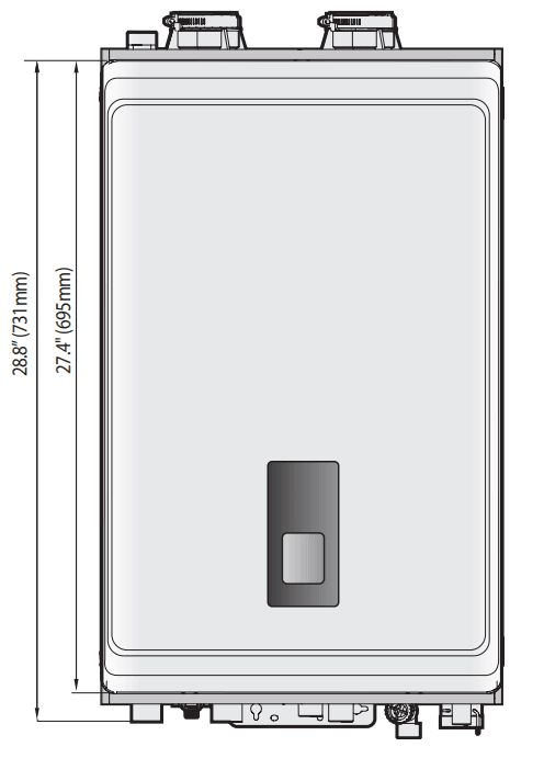
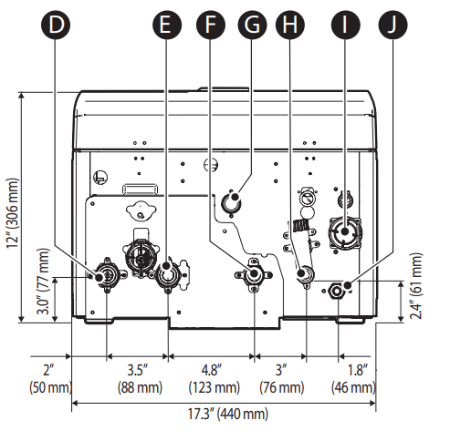
Supply Connections
| Description | Diameter | |
| A | Pressure Relief Valve Adapter | 3/4 in |
| B | Air Intake | 2 in |
| C | Exhaust Gas Vent | 2 in |
| D | Space Heating Supply | 1 in |
| E | Space Heating Return | 1 in |
| F | Hot Water Outlet (DHW) | 3/4 in |
| G | Gas Supply Inlet | 3/4 in |
| H | Cold Water Inlet (DHW) | 3/4 in |
| I | Condensate Outlet | 1/2 in |
| J | Auto Feeder Inlet (Make-up Water) | 1/2 in |
Overhead View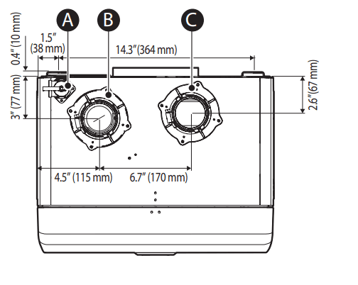
Supply Connections
System Details
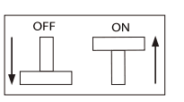
Setting the DIP Switches
The boiler has two DIP switch locations: on the main circuit board (PCB) and on the front panel. Each location has two sets of DIP switches that control the functionality of the boiler. Set the DIP switches appropriately, based on the installation environment and the gas type.
Setting the DIP Switches
Circuit Board DIP Switches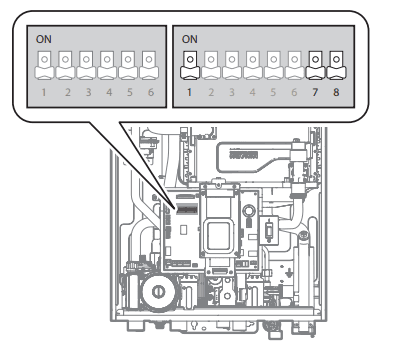
- Set of DIP Switches 1 (Set of 6)
The DIP switches 1 on the circuit board configure the boiler’s model and gas type settings. These configurations are set at the factory and should not be changed. The following tables describe the functions of the DIP switches and their settings.
Switch Function Setting 1 & 2
Operation Status
Normal 1-OFF, 2-OFF Forced Max (2 stage) 1-ON, 2-OFF Forced Min (1 stage) 1-OFF, 2-ON 1 Stage Max 1-ON, 2-ON 3 Reserved – – 4 Reserved – – 5 & 6
Capacity select
NCB-150E 5-ON, 6-ON NCB-180E 5-OFF, 6-OFF NCB-210E 5-ON, 6-OFF NCB-240E 5-OFF, 6-ON - Set of DIP Switches 2 (Set of 8)
The DIP SW 2 on the circuit board configures additional features at the time of installation, such as temperature control modes.Switch Function Setting 1
Temperature Control Return Water 1-ON Supply Water 1-OFF 7
Thermostat or Zone Controller
Unused (Permanent space heating demand) 7-ON
Used 7-OFF 8
Exhaust Thermostat
Temperature Limit Unused (CPVC) 8-ON Setting (PVC) 8-OFF
Setting the Front Panel DIP Switches
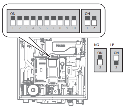
- Set of DIP Switches 1 (Set of 10)
The DIP SW 1 on the front panel configures the temperature unit, well pump, and high altitude settings.SW1 NO. Application Setting Remarks 1 Reserve 2 Temperature Unit °C (Celsius) 2-ON °F (Fahrenheit) 2-OFF 3
Well Pump
Well Pump ON 3-ON Well Pump Mode These settings are to be used with well system when an external pump is wired to the boiler.
Well Pump OFF 3-OFF 4 & 5
High Altitude
0-1,999 ft (0-609 m) 4-OFF, 5-OFF High Altitude Above 2,000 ft (610 m), the boiler will de-rate by 4% for each 1,000 ft (305 m) of altitude gain.
This boiler may be installed at elevations up to 10,100 ft (3,078 m) for use with Natural Gas and 4,500 ft (1,370 m) for use with Propane. To use the boiler at a specific altitude, the DIP switches should be set as described above.
2,000-5,399 ft (610-1,645 m) 4-ON, 5-OFF 5,400-7,699 ft (1,646-2,346 m) 4-OFF, 5-ON 7,700-10,100 ft (2,347-3,078 m) 4-ON, 5-ON 6 Reserve 7 Reserve 8 Reserve 9 & 10
Lime Alarm
Off 9-OFF, 10-OFF Cascade system only (Front Panel: after V1.2)
6 Months Alert 9-ON, 10-OFF 12 Months Alert 9-OFF, 10-ON 12 Months Alert 9-ON, 10-ON - Set of DIP Switches 2 (Set of 2)
The DIP SW 2 on the front panel configures the gas type setting.SW1 NO. Application Setting Remarks 1 Cascade vent Common Vent 1-OFF Cascade system only (Front Panel: after V1.2) Individual Vent 1-ON 2 Gas type Natural Gas 2-OFF Propane Gas 2-ON
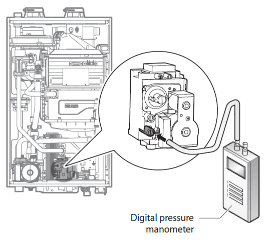
Measuring the Inlet Gas Pressure
- The inlet gas pressure must be maintained between 3.5” and 10.5” WC for natural gas and between 8.0” and 13.5” WC for liquefied propane.
- The appliance and its individual shutoff valve must be disconnected from the gas supply piping system during any pressure testing of that system at test pressures in excess of 1/2 psi (3.5 kPa).
- The appliance must be isolated from the gas supply piping system by closing its individual manual shutoff valve during any pressure testing of the gas supply piping system at test pressures equal to or less than 1/2 psi (3.5 kPa).
To measure the inlet gas pressure:
- Shut off the manual gas valve on the gas supply line.

- Open a hot water faucet. The boiler should turn on and the gas in the gas supply line will be purged.
- Leave the faucet on until the boiler shuts down due to a lack of gas supply, and then turn off the hot water faucet.
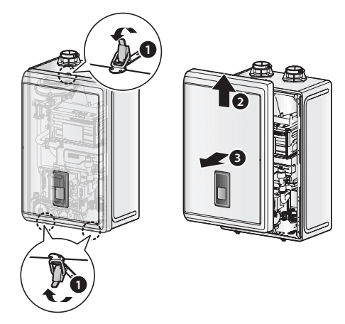
- Unclasp the 3 buckles that fix the cover to the boiler, and then remove the cover by lifting it and pulling it outward.

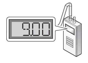
- Loosen the screws indicated in the figure below and connect a manometer to the pressure port. Reset the manometer to zero before use.

- Re-open the manual gas valve and check for leaks.
- Open multiple fixtures that have high flow rates, such as bathtub and shower faucets, to ramp the boiler up to its maximum firing rate.
- When the boiler reaches its maximum firing rate, check the inlet gas pressure reading on the manometer. The gas pressure must fall within the ranges specified on page 18.

Troubleshooting
Error code classification
| Classification | Error Code | Error Level | Function | Self-diagnostic/Action |
|
Combustion System | E003 | 3 | Ignition failure | Manual RESET |
| E004 | 2 | False flame detection | Auto RESET | |
| E012 | 3 | Flame loss | Manual RESET | |
| E016 | 3 | Overheating of heat exchanger | Manual RESET | |
| E030 | 3 1 | Exhaust Overheat: The exhaust limit switch shuts down the unit when the flue temperature exceeds 230 °F(110 °C) for more than 10 seconds. | Manual RESET Auto RESET | |
| E046 | 2 | Abnormal heat exchanger thermistor | Auto RESET | |
| E047 | 3 2 | Abnormal exhaust thermistor | Manual RESET Auto RESET | |
| E060 | 1 | Abnormal Dual Venturi Limit Switch | Auto RESET | |
| Air Supply System | E109 | 3 | Abnormal FAN motor activity | Manual RESET |
| E110 | 3 | Exhaust blockage | Manual RESET | |
| – | – | Abnormal APS (open, short, initial value, or no answer) | No error display | |
| CH System | E205 | 2 | Abnormal H/E outlet: thermistor open or short | Auto RESET |
| E218 | 1 | Abnormal H/E inlet: thermistor open or short | Alarm | |
|
Water supply System | – | – | Abnormal water pressure (Low pressure) | Auto Reset |
| E351 | 3 | Abnormal auto feeder valve | Manual RESET | |
| E352 | 2 | Abnormal water pressure (High pressure) | Auto Reset | |
| E353 | 2 | Abnormal water pressure sensor | Auto Reset | |
| DHW System | E407 | 1 | Hot water outlet1: thermistor open or short | Alarm |
| E421 | 1 | Cold water inlet1: thermistor open or short | Auto RESET | |
| E439 | 3 | Abnormal flow sensor | Auto RESET | |
|
Controller | E515 | 3 | Abnormal PCB | Manual RESET |
| E517 | 3 | Abnormal DIP Switch setting | Manual RESET | |
| E594 | 1 | Abnormal communication in parts of PCB | Alarm | |
| E615 | 3 | Abnormal input & memory | Manual RESET | |
| Installation System | E740 | 2 | Abnormal outdoor sensor | Auto RESET |
| E782 | 1 | Abnormal Main-Panel communication | Auto RESET | |
| E777 | 2 | Abnormal LWCO | Auto RESET |
Error Code List
| Error Code | Sub Code | Function | Self-diagnostic/Action |
|
E001 |
0 |
Overheating of heat exchanger | ● Clean the Strainer ● Check the Pump for proper voltage from PCB(120AC) ● Check for proper flow rate and circulation through the heating line. ● Check the heat exchanger; flush it with a cleaning solution. |
|
E003 |
0 |
Ignition failure | ● Tighten the ground connection screws on the heat exchanger. ● Check to see if the main gas supply valve is open. ● Verify that gas pressure is within operating range. ● Check the gas system and orifice. ● Check Dual Venturi for proper operation. ● Check for proper dipswitch settings (see page 20) |
| E004 | 0 | FALSE flame detection | ● Ensure the ground wire is connected. ● Check the igniter for spark. |
|
E012 |
0 |
Flame loss | ● Tighten the ground connection screws on the heat exchanger. ● Check the main gas line (Is the valve open?). ● Verify gas pressure is within operating range. ● Check gas meter for proper BTU capacity. ● Check flame rod and verify [K] value in DIAGNOSTIC mode. ● Check the intake air filter. ● Check ground wire. ● Check power supply. ● Tighten the ground connection screws on the heat exchanger. |
|
E016 |
0 |
Overheating of heat exchanger | ● Clean the inlet water filter and Strainer. ● Check High Limit Switch. ● Check for proper dipswitch settings (see page 20) ● Check the 3-way valve. ● Check the heat exchanger; a flush may be necessary. ● Turn OFF the system for at least 30 minutes then restart. |
|
E030 |
0 | Exhaust Overheat: The exhaust limit sensor shuts down the unit when the flue temperature exceeds 230 °F (110 °C) for more than 10 seconds. | ● Turn OFF the system for at least 30 minutes then restart. ● Clean the inlet water filter and Strainer. ● Check the exhaust thermistor and verify [P] value in DIAGNOSTIC mode. ● Check the heat exchanger; a flush may be necessary. |
| E046 | 2 | Abnormal heat exchanger High Limit Switch | ● Check heat exchanger High Limit Switch connection ● Check for proper connection to the PCB. |
| E047 | 1 | Abnormal exhaust thermistor (open) | ● Check the exhaust thermistor connection. |
| 2 | Abnormal exhaust thermistor (short) | ● Check for proper connection to the PCB. | |
|
E060 | 1 | Abnormal Dual Venturi Limit Switch operation (ON) | ● Check the Dual Venturi connection. |
| 2 | Abnormal Dual Venturi Limit Switch operation (Close OFF) | ● Test Dual Venturi for proper operation using TEST mode. | |
| 3 | Abnormal Dual Venturi Limit Switch operation (Open ON) | ● Check the gas orifice for obstructions. |
| Error Code | Sub Code | Function | Self-diagnostic/Action |
| E109 | 0 | Abnormal fan motor activity | ● Check and clean the intake air filter. ● Verify proper voltage from PCB. ● Check and clean the fan motor. |
|
E110 | 1 | Exhaust blockage (checking the FAN) | ● Check the intake/exhaust/condensate drain pipe for obstructions.(ice, snow, wildlife, etc) |
| 2 | Exhaust blockage (Using hot water) | ● Check and clean the intake air filter | |
| 3 | Exhaust blockage (using space heating) | ● As a temporary solution for troubleshooting purposes, restart the unit and/or remove the front cover. | |
| E205 | 1 | Abnormal Heating supply thermistor (Open) | ● Check the thermistor. (Connector, Wire, Resistance of sensor) ● Check the Pump operation ● Replace the thermistor. |
| 2 | Abnormal Heating supply thermistor (Short) | ||
| E218 | 1 | Abnormal Heating return thermistor (Open) | ● Check the thermistor. (Connector, Wire) ● Check thermistor voltage from PCB and resistance values. ● Replace the thermistor. |
| 2 | Abnormal Heating return thermistor (Short) | ||
| E351 | 0 | Abnormal Auto feeder valve (make-up water) | ● Check the auto feeder valve |
| E352 | 1 | Abnormal Cold water inlet2: thermistor (Open) | ● Check the auto feeder valve ● Check incoming water pressure and any activity at PRV. |
| E353 | 1 | Abnormal water pressure sensor (Open) | ● Check the water pressure sensor. |
| 2 | Abnormal water pressure sensor (Short) | ||
| E407 | 1 | Abnormal Hot water outlet: thermistor (Open) | ● Check the thermistor. (Connector, Wire, Resistance of sensor) ● Check the Pump operation ● Replace the thermistor.” |
| 2 | Abnormal Hot water outlet: thermistor (Open) | ||
| E421 | 1 | Abnormal Cold water inlet: thermistor(Open) | ● Check the thermistor. (Connector, Wire) ● Check thermistor voltage from PCB and resistance values. ● Replace the thermistor. |
| 2 | Abnormal Cold water inlet: thermistor(Short) | ||
|
E515 | 1-2, 10 | Abnormal monitoring device of PCB | ● Check the PCB connection. ● Reset the PCB power. |
| 3-4 | Abnormal communication between PCB and Gas V/V | ● Check the connection between PCB and Gas V/V ● Check the Resistance of Gas V/V | |
| 5-7 | N/A | N/A | |
| 8 | Abnormal communication between PCB and Ignitor | ● Check the PCB connection ● Check the Ignitor | |
| 9 | Abnormal communication between PCB and FAN | ● Check the PCB connection ● Check the Fan | |
| 11-12 | Abnormal communication between PCB and Dual Venturi | ● Check the PCB connection ● Check the Dual Venturi | |
| E517 | 0 | Abnormal dip switch setting | ● Check the dip switches on the front panel and PCB. |
| E594 | 0 | Abnormal EEPROM of PCB | ● Check the PCB. |
| Error Code | Sub Code | Function | Self-diagnostic/Action |
|
E615 | 0 | Abnormal input data from High limit switch of the Heat exchanger | ● Check the HTL and connection. ● Check the PCB. |
| 1 | Abnormal input data from the exhaust sensor | ● Check the exhaust sensor wiring connection ● Check the exhaust sensor | |
| 2 | Abnormal input data from flame rod | ● Check the flame rod wiring connection. ● Check the flame rod. | |
| 3-14 | Abnormal memory of PCB | ● Check the PCB | |
| 15 | Below is the range of input data from the Pressure sensor | ● Check the Pressure sensor wiring connection ● Check the output voltage of the pressure sensor | |
| 16 | Over the range of input data from the Pressure sensor | ||
|
E740 | 1 | Abnormal outdoor temperature sensor (Open) (appears only when the outdoor reset curve is enabled). |
1. Ensure that the outdoor reset curve is configured properly. 2. Check the outdoor temperature sensor wiring connection. |
| 2 | Abnormal outdoor temperature sensor (Short) (appears only when the outdoor reset curve is enabled). | ||
| E777 | 0 | Abnormal operation: LWCO | ● Check the LWCO wiring connection ● Ensure that the system water level is appropriate. ● Add make-up water to the system if necessary. ● Check for proper voltage from connector(24VAC). |
| E782 | 0 | Abnormal Main-Panel communication | ● Check the connection between PCB and Panel ● Check the PCB. |
If any of the above solutions do not resolve the problem with the Boiler, contact Navien’s Technical department at 1-800-519-8794. There will be error codes displayed on the front panel and recorded on the PCB board (within the unit) for any problems or failures that occur with the Boiler.
For more manuals by Navien, visit ManualsLibraryy
Navien NCB-150E Condensing Combi-Boilers-FAQs
Why does my Navien tankless water heater keep tripping the breaker?
This could be due to two main issues:
1. Water leaking onto the unit’s wiring, causing the breaker to trip.
2. An internal electrical fault within the heater.
What is the difference between Navien NCB and NFC series?
Both are high-efficiency, high-capacity gas combi-boilers. The NCB-H Series and NFC-H Series share similar efficiency, but the NFC-H Series offers a higher output.
What is the ideal flow temperature for a combi boiler?
A recommended flow temperature is 60°C, though it may need adjustment based on your home’s insulation and heating needs.
What is the flow rate of the Navien NCB-H combi boiler?
The NCB-H Series provides:
1. Maximum DHW BTU/h: 210,000
2. Flow rate: 5.4 GPM at a 70°F temperature rise
3. DHW turndown ratio: 15:1
Why does my Navien water heater keep turning on and off?
Frequent on-and-off cycling may indicate a failing control board.
How many breakers are needed for a tankless water heater?
Electric tankless water heaters typically require 40 to 120 amps. To determine the correct breaker size, multiply the required amperage by 1.25. For an 80-amp heater:
80A × 1.25 = 100A, so a 100-amp breaker is required.
Do tankless water heaters have fuses?
Yes, they contain a cutoff fuse that prevents overheating by shutting off the gas valve if a heat exchanger breach or gasket failure occurs.
How does a combi boiler work?
Combi boilers heat water directly from the mains when needed. When the room thermostat detects a temperature drop, the boiler activates, heating water for central heating and hot water on demand.